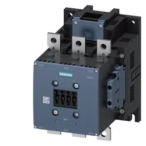
It's a screw-fixing unit with an integrated auxiliary switch, rated for a 575-600 V coil. That coil voltage range puts it squarely in North American 600 V class installations, not the common 24 VDC or 120 VAC control circuits you see in European panels. The contactor handles multiple duty classes: AC-1 (resistive loads) at up to 800 switching cycles per hour, AC-3 (squirrel-cage motor starting) at 500 cycles per hour, and AC-4 (plugging/inching) at 130 cycles per hour.
That's enough to fit into tight enclosures or odd-angle panels. Screw fixing through a single 11 mm hole — no DIN rail clip on this frame size, so plan for drilling and tapping the backplate. That forward clearance is the one that catches people — 20 mm means the arc chute needs breathing room, especially at higher switching frequencies. Panel builders should account for that when laying out the gland plate. Dimensions are 210 mm high, 145 mm wide, 202 mm deep — a substantial footprint.
Terminal and wiring
Main power terminals accept stranded wire from 70 to 240 mm² — that's serious cable, typical for 200+ A motor circuits. The coil terminals are screw-type, accepting 2x (0.5 to 1.5 mm²) solid, 2x (0.75 to 2.5 mm²) solid, or up to 2x (0.75 to 4 mm²) stranded. That's standard for control wiring, but the 4 mm² max on stranded means you can parallel two smaller conductors if needed. Auxiliary contact ratings: 10 A at 24 V, 2 A at 48 V, 2 A at 60 V, 1 A at 110 V. Those are the switching limits for the built-in auxiliary switch — useful for interlocking or status feedback to a PLC input. The 24 V rating is generous; the 110 V derating is steep, so don't plan on switching multiple 120 VAC loads through it.
That's the mechanical endurance, not the electrical — electrical life depends on the switching duty and load current, which will be lower under AC-4 or high-current AC-3 conditions.