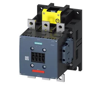
The 3RT1065-6SP36-3PA0: The listed MTBF of 75 a (years) reflects a design reliability target for continuous duty under rated conditions. For a power contactor in a 24/7 process line, this figure informs spare-parts planning and preventive maintenance intervals — it is not a warranty or guaranteed life, but a statistical mean time between failure used in system reliability calculations. The S10 frame size (210 mm height, 145 mm width, 202 mm depth) determines the panel cutout and the busbar or cable routing space needed. The 202 mm depth must be checked against enclosure depth, especially in shallow wall-mount cabinets where rear clearance for arcing and cable bending is limited. Mounting is via screw fixing with vertical mounting surface, rotatable ±90° and tiltable ±22.5° front-to-back.
Switching Performance and Duty Ratings
The contactor is rated for AC-1 (resistive) switching at up to 500 operations per hour, AC-2 (slip-ring motor) at 250 ops/h, AC-3 (squirrel-cage motor starting) at 500 ops/h, and AC-4 (plugging/inching) at 130 ops/h. The AC-3e rating also reaches 500 ops/h. These duty-cycle limits govern the maximum switching frequency without overheating the contacts — exceeding them accelerates contact wear and may cause welding. The coil's rated value is 200-277 V with an initial pickup of 0.8 times rated and a full-scale dropout of 1.1 times rated — meaning the coil will hold in at 160 V minimum and will drop out reliably above 305 V.
The main power circuit accepts stranded conductors from 70 to 240 mm² — sized for the full rated current of the S10 frame. The coil and auxiliary connections use screw-type terminals accepting solid or stranded wire: 2x (0.5 to 1.5 mm²), 2x (0.75 to 2.5 mm²), or max 2x (0.75 to 4 mm²). An auxiliary switch is included as standard.