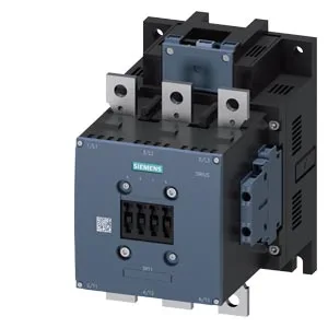
Active production — SIRIUS S10 with 72 V DC coil
The 3RT1065-6XJ46-0LA2: The contactor measures 210 mm high by 145 mm wide by 202 mm deep, with screw fixing as the fastening method. The mounting position allows rotation up to ±90° on a vertical surface and tilting ±22.5° front-to-back, giving flexibility in tight enclosures where the DIN rail is not an option.
Termination and auxiliary switching capacity
This range covers most motor-circuit wiring from control to power feeds — the 4 mm² max per terminal handles the line-side connection for a contactor this size. For a 72 V DC coil circuit, the auxiliary contacts are comfortably overspecified — the 2 A at 60 V rating gives headroom for pilot-duty loads like PLC inputs or indicator lamps.
Switching frequency and thermal limits
Maximum switching rates are class-specific: 700 operations per hour in AC-1 (resistive), 500 in AC-3 (squirrel-cage motor start/run), 250 in AC-2 (slip-ring motor), and 130 in AC-4 (plugging/inching). The DC-1, DC-3, and DC-5 ratings all cap at 350 ops/h. These numbers set the duty-cycle ceiling — a conveyor running 30 starts per hour is well within the AC-3 limit, but a welding transformer switching every 10 seconds would push the AC-1 envelope. The mechanical lifetime is 10 million operations typical — a figure that assumes proper coil voltage and contactor protection; actual service life depends on switching frequency and load current.
Coil timing and clearance requirements
The initial dropout voltage factor is 0.7 (70% of rated voltage), and the full-scale pickup factor is 1.25 (125% of rated). This means the contactor will drop out at about 50 V DC and must see at least 90 V DC to pull in reliably — important when sizing the control transformer and rectifier. The single mounting hole has an 11 mm diameter. These clearances are the minimum air gap to adjacent metalwork or other devices — a panel layout that respects them avoids arc flash tracking and meets IEC 60947-1 spacing requirements.