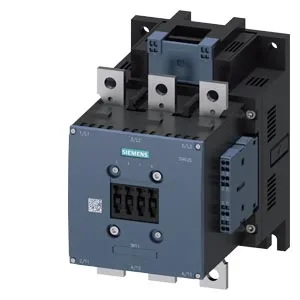
S10 Frame, 202 mm Depth — Panel Fit Reality
The 3RT1066-2AD36 is a SIRIUS power contactor in the S10 frame size, measuring 202 mm deep by 145 mm wide by 210 mm tall. Mounting is via screw fixing through an 11 mm hole — not DIN rail, so plan for a drilled backplate or adapter plate if the existing panel uses a rail footprint. Clearance requirements are tight: 10 mm upwards and downwards, 20 mm forwards, and 10 mm at the side. That forward clearance is the one that catches people — the arcing space plus the spring-type terminal access needs that 20 mm, not the 10 mm you might budget from the side gaps.
Duty-Cycle Ceilings — AC-3 vs AC-4 Reality
The rated switching frequency depends entirely on the duty class. In AC-3 (motor starting, breaking during run) it manages 500 operations per hour — the same ceiling applies for AC-3e. AC-1 (resistive loads) allows 750 ops/h, AC-2 (slip-ring motors) drops to 250, and AC-4 (plugging, inching) is the bottleneck at 130 ops/h. If your application cycles faster than that, the contactor will overheat the arc chamber. Mechanical life is rated at 10 million operations typical — that's the contactor body itself, not the contacts. Electrical life will be lower and depends on the switching current and duty class; the AC-4 figure of 130 ops/h is a strong hint that heavy inching duty wears the contacts fast.
Coil and Terminal Wiring — Spring-Type on the Coil, Screw on the Power
The magnet coil uses spring-type terminals — push-in or screwdriver-actuated, accepting 2x (0.25 to 2.5 mm²) solid or stranded. The main power circuit uses screw terminals sized for 70 to 240 mm² stranded cable. That's a heavy lug — the 11 mm mounting hole matches the bolt-down bus bar approach for the power side. Coil voltage is 42-48 V AC/DC with a pickup threshold of 0.8× rated and a dropout of 0.9× at 50/60 Hz. The operate time is 40-80 ms AC or DC, with an arcing time of 10-15 ms. That's consistent for a contactor this size — the coil dropout margin is tight, so if your control voltage sags below 38 V at 48 V nominal, the contactor drops out.
Auxiliary Contact Ratings and Ambient Limits
An auxiliary switch is built in — rated 10 A at 24 V, 2 A at 48 V or 60 V, and 1 A at 110 V. These are the thermal current ratings for the auxiliary contacts; they derate with voltage and inductive loads. If you need more auxiliary poles, the S10 frame accepts add-on blocks, but this base unit carries one set. Operating temperature range is -25 to +60 °C, storage from -55 to +80 °C. The mounting position allows vertical surface with ±90° rotation and ±22.5° tilt front-to-back — useful for tight enclosures where the contactor must sit at an angle.