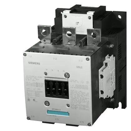
It carries a 110... 127 V AC coil with screw-type terminals and includes an integrated auxiliary switch.
The magnet coil operates on a 110... 127 V AC supply and is terminated via screw-type terminals. Pickup is guaranteed at 0.8 of rated voltage, and the dropout threshold sits at 1.1 times rated value — meaning the contactor holds in cleanly down to about 88 V and drops out reliably if the control voltage rises above 140 V. That arcing window matters for contactor life on inductive loads: the arc quenches fast enough to keep contact erosion within the rated mechanical life of 10 million operations.
Power Circuit and Wiring
Main pole wiring accepts stranded conductors from 70 up to 240 mm² — substantial cable for the S10 frame. The auxiliary circuit uses screw terminals sized for solid or stranded wire: 2x (0.5... 1.5 mm²), 2x (0.75... 2.5 mm²), or max 2x (0.75... 4 mm²). The auxiliary contacts are rated at 10 A at 24 V, 2 A at 48 V and 60 V, and 1 A at 110 V — typical for pilot-duty control circuits. You can expect to land the main power with ring lugs on the 11 mm mounting holes and terminate the aux wiring directly into the screw cages.
Mounting is via screw fixing on a vertical surface. The contactor can be rotated ±90° or tilted ±22.5° front-to-back, giving panel builders flexibility in tight enclosures. The SIRIUS S10 frame dimensions are 210 mm height, 145 mm width, and 202 mm depth — a substantial footprint that needs planning in the gland plate and DIN-rail layout.
Duty Cycles and Application
Switching frequency varies by duty category: AC-1 (resistive) allows up to 750 ops/h, AC-2 (slip-ring motors) 250 ops/h, AC-3 (squirrel-cage motors) 500 ops/h, and AC-4 (plugging/inching) 130 ops/h. The AC-3e rating also caps at 500 ops/h. For a motor starting application, the 500 ops/h AC-3 ceiling is the governing number — it sets the maximum start frequency before thermal limits kick in. If the line runs a rapid-cycle load, stay under that rate.