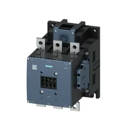
Its main-pole cable range accepts 70 to 240 mm² stranded conductors, so it handles the high-current feed from a distribution bus or large motor branch. The magnet coil is rated 220-240 VAC, with screw-type terminals for the coil connection. Mounting is by screw fixing, not DIN rail — plan for four M8 bolts through 11 mm holes on a vertical surface, with ±90° rotation and ±22.5° tilt allowed.
The contactor's maximum operating frequency varies sharply by duty class: 750 cycles per hour in AC-1 (resistive), 500/h in AC-3 (squirrel-cage motor start/run), and 130/h in AC-4 (plugging/inching). For AC-3e (enhanced motor switching) the limit is also 500/h. AC-2 (slip-ring motor) drops to 250/h. These are the thermal limits of the contactor's arc chamber and bimetallic strip — exceeding them in a given duty class shortens contact life. That means the contactor can handle fast cycling in a conveyor or pump start sequence, but not continuous inching at high rates.
Auxiliary contact ratings and wiring
The auxiliary contacts are rated: 10 A at 24 V, 2 A at 48 V, 2 A at 60 V, and 1 A at 110 V. These are the thermal current limits for the auxiliary circuit — use them for PLC inputs, status lamps, or interlocking relays. The auxiliary terminals accept solid or stranded conductors: 2x 0.5-1.5 mm², 2x 0.75-2.5 mm², or max 2x 0.75-4 mm². The coil terminals are screw-type, so you'll need a screwdriver for both coil and auxiliary wiring.
Mounting dimensions and clearances
The contactor measures 210 mm high, 145 mm wide, and 202 mm deep. Mounting is by screw fixing through one 11 mm hole per pole — four bolts total. These are the arc-flash and cooling clearances; respect them to avoid tracking or thermal derating.