Duty-cycle capability and switching frequency
The contactor is rated for different switching frequencies depending on the duty class: 750 operations per hour in AC-1 (resistive), 500/h in AC-3 (motor start/run), and 130/h in AC-4 (plugging/inching). The AC-3e rating matches the AC-3 figure at 500/h. For a conveyor drive cycling every 30 seconds, the AC-3 limit of 500/h gives headroom; a reversing starter doing frequent inching will hit the AC-4 ceiling of 130/h and may need a larger frame or forced cooling. Under AC-3 duty at rated load, electrical life will be lower; the mechanical figure tells you the actuator and spring set are built for a long service interval in a cycling application.
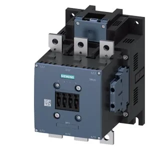
Mounting is via screw fixing through an 11 mm hole, one hole per contactor. That is a through-bolt pattern, not DIN rail — so the panel backplate needs drilled and tapped holes or a mounting rail adapter. The size S10 frame measures 210 mm high by 145 mm wide by 202 mm deep, which is a substantial footprint; plan for gland plate clearance and busbar routing. That allows the contactor to be oriented for busbar access or cable entry without derating, as long as the vertical plane is maintained. These are minimums for arc flash containment and cooling airflow — crowding the contactor against the enclosure wall or another device will reduce the switching frequency capability.
Control circuit and auxiliary contacts
The magnet coil uses screw-type terminals, accepting solid or stranded conductors: 2x (0.5 to 1.5 mm²), 2x (0.75 to 2.5 mm²), or max 2x (0.75 to 4 mm²). That covers standard control wiring up to 12 AWG. The contactor includes an auxiliary switch, with ratings of 10 A at 24 V, 2 A at 48 V and 60 V, and 1 A at 110 V — sufficient for signaling to a PLC input or a pilot light. That is typical for a contactor of this size; the DC coil version avoids the hum and dropout delay of an AC coil rectifier.