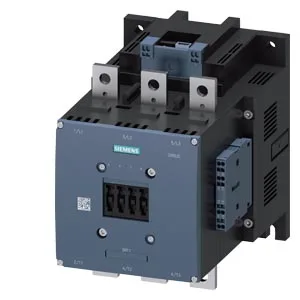
The 110 VDC coil pulls in with a 0.7 initial-value factor and holds with an arcing time of 10–15 ms. The auxiliary switch is factory-fitted, saving a separate aux block order.
Fastened via screw fixing with a single 11 mm hole. The mounting surface must be vertical; the contactor can be rotated ±90° or tilted ±22.5° front-to-back. These spacings govern panel layout — pack too tight and arc flash or heat dissipation is compromised. Dimensions: 160 mm wide, 214 mm high, 225 mm deep. The 225 mm depth is the full body depth including arc chamber; verify clearance behind the panel door before routing cables.
Solid or stranded conductors: 2x (0.25–2.5 mm²) per clamp. Accepts ferruled stranded wire up to 2.5 mm²; strip length follows standard 8–10 mm practice. No special lug required.
Switching frequencies by duty class
Maximum switching rates per hour: AC-1 (resistive) 500 1/h, AC-2 (slip-ring motor) 170 1/h, AC-3 (squirrel-cage motor) 420 1/h, AC-3e (enhanced) 420 1/h, AC-4 (plugging/inching) 130 1/h, DC-1 (resistive) 250 1/h, DC-3 (shunt motor) 200 1/h, DC-5 (series motor) 200 1/h. These are mechanical design limits — the real limit in a motor-start application is the thermal load of the starting current, not the contactor alone.
Lifecycle stage is current production. No phase-out or last-time-buy notice has been issued.