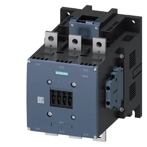
It carries a 200... 277 V AC coil with screw-type terminals, and the main circuit accepts stranded conductors from 70 up to 240 mm² — enough for heavy feeder or motor branch circuits. Keep 10 mm clearance at the sides, 10 mm upward, 20 mm forward, and 10 mm downward for arc venting and heat dissipation.
Coil and control circuit — what the ratings mean
The coil pulls 0.4 A at 50 Hz and 0.4 A at 60 Hz at the rated 200... 277 V. Pickup and dropout timing is 80... 100 ms on both AC and DC supplies, and arcing time runs 10... 15 ms. The coil hold-in range starts at 0.8 × rated voltage (160 V minimum) and the full-scale overvoltage limit is 1.1 × rated (305 V). That 0.8 initial value means the contactor stays pulled in through a moderate brownout — useful if you're on a shared distribution with motor-start dips. Auxiliary switch contacts are built in, rated at 10 A at 24 V, 2 A at 48 V and 60 V, and 1 A at 110 V — enough for PLC input sensing or relay interlocking without an add-on block.
Switching duty and mechanical life
Maximum operating frequency varies by duty: 500 cycles/hour in AC-1 (resistive), 420 in AC-3 (squirrel-cage motor starting), 420 in AC-3e (enhanced motor), 170 in AC-2 (slip-ring motor), and 130 in AC-4 (plugging/inching).
Wiring and termination details
The coil uses screw-type terminals accepting 2 × (0.5... 1.5 mm²) solid or 2 × (0.75... 2.5 mm²) stranded, max 2 × (0.75... 4 mm²). Main power terminals take 70... 240 mm² stranded — that's a serious lug range, typically 2/0 to 500 MCM in AWG terms, for high-current motor circuits or feeder taps. One mounting hole per terminal, 11 mm diameter, for standard M10 hardware.