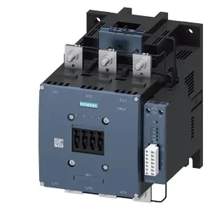
SIRIUS S12 — what the frame size tells you about panel fit
The 3RT1076-6PF35: This is a Siemens SIRIUS Size S12 power contactor — the frame size tells you the mounting hole pattern and the bus-bar / cable lug spacing are fixed for this class. It uses screw fixing, not DIN-rail snap-on, so plan for drilled and tapped backplate or threaded inserts. The body measures 214 mm high by 180 mm wide by 225 mm deep. That depth includes the arc chamber and the coil housing — it's a deep unit, so check the gland-plate clearance and the door swing if the contactor sits near the enclosure front. Clearance distances are specified: 10 mm upwards and downwards, 20 mm forwards, and 10 mm at the sides. Those are minimums for arc flash and heat dissipation — don't crowd it against cable ducts or other devices.
Coil voltage and termination — screw terminals, 96-127 V range
The magnet coil is rated for 96-127 V, covering both AC and DC supplies. The coil connection uses screw-type terminals — standard for panel wiring, but torque them to the manufacturer's spec to avoid loose connections under vibration. Operating delay is 80-100 ms for both AC and DC. That's the time from coil energisation to main contact closure — factor it into your sequence timing if this contactor is in a safety or interlock chain. Arcing time on dropout is 10-15 ms. That's the interval between coil de-energisation and arc extinction — relevant for contact erosion estimates and for coordinating with upstream overcurrent devices.
Main and auxiliary conductor sizing
Main pole connections accept stranded copper from 70 mm² up to 240 mm². That's a heavy cable range — you'll be using compression lugs or two-hole palm lugs with the single 11 mm hole. Auxiliary switch terminals accept 2x 0.5-1.5 mm² solid or 2x 0.75-2.5 mm² stranded, with a maximum of 2x 0.75-4 mm². The auxiliary switch is present — these are the smaller screw terminals on the side of the contactor. Auxiliary contact ratings: 10 A at 24 V, 2 A at 48 V, 2 A at 60 V, 1 A at 110 V. These are the make/break capacities for the auxiliary contacts — useful for pilot duty or PLC input circuits.
Switching frequency and duty cycle limits
Maximum switching rates per duty class: AC-1 (resistive) 500 operations/hour, AC-2 (slip-ring motor) 170 ops/h, AC-3 (squirrel-cage motor) 420 ops/h, AC-4 (plugging/inching) 130 ops/h. The AC-3e rating matches AC-3 at 420 ops/h. These are the thermal limits of the contactor — exceeding them shortens contact life and can cause welding. For high-cycle applications like conveyor indexing, stay well below the AC-3 ceiling.
Environmental limits and mounting orientation
Operating ambient temperature range is -25 to +60 °C; storage range is -55 to +80 °C. The contactor can be mounted on a vertical surface, rotatable ±90° and tiltable ±22.5° forward/back. That gives flexibility in tight enclosures — just keep the arc chamber orientation within those limits. Mechanical endurance is rated at 10 million operations typical. That's the mechanical life before the contactor wears out mechanically — electrical life will be lower and depends on the switching current and duty class.