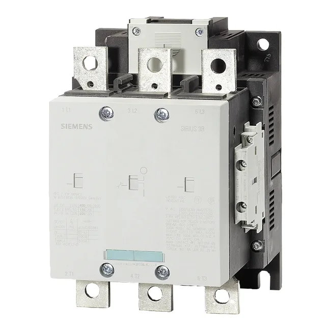
The 3RT1264-6AT36: The S10 frame is the mechanical platform that determines mounting footprint and main-pole spacing. The contactor accepts stranded power conductors from 70 to 240 mm² — that range covers most motor feeds from roughly 150 A up to 400 A class, so verify your cable size lands within that window before committing the panel layout. Switching frequency depends on duty class: at AC-1 (resistive loads) it can cycle 800 times per hour, at AC-3 (squirrel-cage motors, starting only) 750 cycles per hour, and at AC-4 (plugging, inching, reversing) it drops to 250 cycles per hour. The AC-4 limit is the one that governs a reversing or jogging application — if your line cycles a motor in both directions more than four times a minute, this contactor will exceed its rated mechanical life before the vacuum bottle wears out. Auxiliary control wiring uses screw-type terminals accepting 2x (0.5... 1.5 mm²), 2x (0.75... 2.5 mm²), or max 2x (0.75... 4 mm²) solid or stranded conductors. That gives flexibility for daisy-chaining interlock signals without needing a separate terminal block.
Fastening is by screw fixing through a single 11 mm hole. The overall dimensions are 210 mm height, 145 mm width, 206 mm depth. That clearance is for arc venting and heat dissipation — do not crowd the vacuum bottle side against a cable duct or panel wall. Arcing time at break is 10... 15 ms. Those numbers matter for coordination with upstream fuses or circuit breakers — the total fault-clearing time is the sum of the protection device's response plus the contactor's arcing time, so a 15 ms arc at 600 V needs a fuse that can hold through that half-cycle without melting.