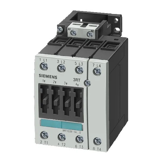
Siemens 3RT1336-1AT60 SIRIUS Power Contactor — S2 Frame, 11 kW AC-2 Motor Duty
Termination and Wiring — Screw-Type Main and Auxiliary Circuits
Both the main current circuit and the auxiliary/control circuit use screw-type terminals. The main circuit accepts solid conductors from 2x (0.5... 1.5 mm²) up to max 2x (0.75... 4 mm²), and stranded conductors from 2x (0.75... 25 mm²). For the control circuit, solid or stranded 2x (0.75... 16 mm²). AWG equivalents for the main contacts are 2x (18... 2). The minimum permissible cross-section at both 40 °C and 60 °C is 16 mm² — that's the smallest wire that can carry the rated current without exceeding the terminal temperature rise. The protection recommendation for type of assignment 2 (coordination with short-circuit protective device) is a gL/gG fuse rated 63 A. That's the fuse size that limits let-through energy to protect the contactor during a bolted fault.
Duty Ratings and Switching Performance
Beyond the AC-2 motor rating, the contactor carries specific switching capacities for auxiliary contacts at various voltages: 10 A at 24 V, 2 A at 60 V, 1 A at 110 V, 0.3 A at 220 V, 6 A at 230 V, and 3 A at 400 V (–). These are the make/break ratings for the auxiliary contact block — useful for interlocking, status feedback, or PLC input circuits. The arcing time is 10 to 15 ms, and the mechanical life is typical 10,000,000 operations. At AC-1 maximum (resistive load), the switching rate is 1,000 cycles per hour. The coil operates across a voltage range of 0.8 to 1.1 times the rated control supply voltage at 60 Hz, with a pick-up time of 10 to 30 ms at AC. The rated control supply voltage at 60 Hz is 600 V — that's the coil voltage, not the main circuit. For a 24 VDC coil variant, the 10 A rating at 24 V applies to the auxiliary contacts, not the coil itself.