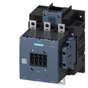
The coil accepts a rated control supply voltage of 240 to 277 V, and it operates on either AC or DC (type of voltage AC/DC). This dual-voltage AC/DC coil simplifies panel design when the control voltage could be either — no need to swap coil variants between an AC control transformer and a DC power supply. The coil terminals are screw-type, which is the standard for this frame size and suits panel wiring with ferruled or solid conductors. It includes an auxiliary switch with built-in auxiliary contacts for status feedback or interlocking. The contactor mounts via screw fixing (fastening method) and has a single 9 mm diameter mounting hole.
The main circuit accepts stranded conductors from 25 to 120 mm². That's a heavy lug range — you're landing cables sized for a 100 A+ motor circuit, not a small control feeder. The auxiliary circuit uses smaller terminals: solid or stranded 2x (0.5 to 1.5 mm²), 2x (0.75 to 2.5 mm²), max 2x (0.75 to 4 mm²). This matches typical control wiring sizes. The -25 °C low end means it's usable in unheated enclosures in cold climates, but below that you'd need a cabinet heater. The +60 °C upper limit is typical for contactors in a ventilated panel — if your enclosure runs hotter, you'll need to derate or provide forced cooling. Physical dimensions: height 172 mm, width 120 mm, depth 170 mm. This is a substantial three-pole contactor — plan for the depth when laying out the backplate, especially if using deep cable lugs or a rear-mounted bus system. Clearance to adjacent components: 10 mm upwards and downwards, 10 mm to the side, and 20 mm forward.
There is no need to hunt surplus or broker channels. If you are filling a BOM line for a new panel or replacing a failed unit in an existing installation, this is the direct drop-in part.