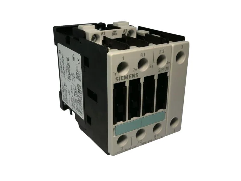
It mounts on a 35 mm DIN rail per DIN EN 50022, with screw and snap-on fixing, and fits a panel footprint of 85 mm high by 61 mm wide by 91 mm deep. The coil is wound for 24 V at 50 Hz, drawing 7.8 VA at 50 Hz. At 60 Hz the power factor is 0.24, which matters if you're feeding the coil from a 60 Hz supply — the inrush and hold characteristics shift, so confirm the pickup and dropout voltages against your control transformer.
The main contacts are rated 25 A per pole for both NO and NC configurations. For AC-1 the maximum switching rate is 1,000 operations per hour. The auxiliary circuit and main circuit both carry a rated impulse withstand voltage of 6 kV.
Wiring and Mounting Reality
Terminals accept solid or stranded conductors: 2x (0.5 to 1.5 mm²), 2x (0.75 to 2.5 mm²), or a maximum of 2x (0.75 to 4 mm²). That's per clamp, so you can double up smaller wires for daisy-chaining control circuits. The screw-type terminals are standard for the main current circuit — no cage-clamp option on this variant. That gives you options when the panel layout is tight, but keep the coil vertical for reliable dropout — horizontal mounting can shift the pickup voltage. That's fast enough for most motor starting but not for DC switching — the contactor is specified for AC circuits; DC ratings are separate and lower.
Electrical life depends on the load: at rated AC-3 current expect roughly 1 million operations before contact wear requires replacement. The contacts are not user-replaceable on the S0 frame; the whole contactor is swapped when worn.