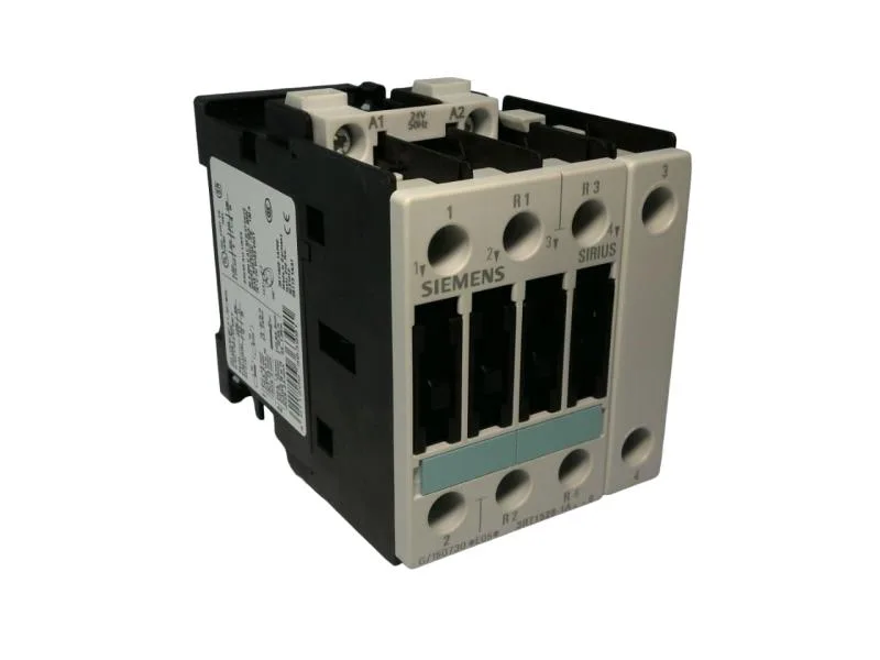
Its 61 mm width, 85 mm height, and 91 mm depth fit the standard S0 panel footprint — no extra gland-plate allowance needed for this frame. This covers most enclosure orientations without derating, provided the vertical surface requirement is met.
The coil is wound for 400 V at 50 Hz, drawing 7.8 VA at 50 Hz and 0.24 A at 60 Hz. For a controls integrator wiring a 400 V control transformer: the coil inrush is modest, so a standard 400 V control circuit breaker sized for the transformer kVA will handle it. No separate coil suppression is called out in the spec, but for inductive loads downstream of the auxiliary contacts, verify free-wheel diode polarity if you add one.
Main and auxiliary circuit ratings
The main circuit is rated for an impulse withstand voltage of 6 kV. The auxiliary circuit shares the same 6 kV rating. Per NO and per NC auxiliary contacts are both rated at 25 A. The operating current at AC-12 (control circuit, resistive loads) is 10 A maximum. For the main circuit, the wire range is screw-type terminals accepting 2x (0.5 to 1.5 mm²), 2x (0.75 to 2.5 mm²), or max 2x (0.75 to 4 mm²) solid or stranded. The maximum conductor size for AC-1 duty is 10 mm².