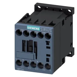
Screw-type coil terminals are standard; the main contact set is rated for 20–12 AWG (solid or stranded 0.5–4 mm²) and the auxiliary switch is included on the front face for status feedback or interlocking.
At 58 mm height and 73 mm depth, it clears most shallow gland-plate enclosures.
Duty Cycle and Switching Frequency
Maximum switching rate depends on the load category: 1000 operations/hour in AC-1 (resistive), 750/h in AC-3 (motor start/run), and 250/h in AC-4 (plugging/inching). For AC-3e (enhanced motor switching) the same 750/h limit applies. These are the thermal limits of the contactor — exceeding them shortens mechanical life, which is rated at 30 million typical operations.
Auxiliary Contact Ratings and Wire Range
The built-in auxiliary switch handles 10 A at 24 V, 2 A at 48/60 V, 1 A at 110 V, 0.9 A at 125 V, 0.3 A at 220 V, and 3 A at 400 V — enough for PLC input sensing or interposing relay control without an add-on block. Wire terminations accept 2x (0.5–1.5 mm²), 2x (0.75–2.5 mm²), or 2x 4 mm² solid or stranded, which covers most control-circuit wiring in North American and European panels.
Environmental Range
The arcing time is 10–15 ms at AC, and the magnet coil operates at 60 Hz with a 0.25 s operating time. These specs matter for cold-store or high-temp panel environments — the contactor holds its rated current across the operating band without derating.