The 3RT2015-1BB41-0CC0: The 24 VDC coil (rated value 24 V) draws an initial inrush of 0.8 A and holds at a lower sealed current — critical for sizing your 24 VDC power supply and verifying the PLC output card can drive the coil without a separate interposing relay. The main contacts are rated for AC-1 resistive loads at up to 1,000 switching cycles per hour, AC-3 motor loads at 750 cycles/hour, and AC-4 (plugging/reversing) at 250 cycles/hour. For AC-3e (high-efficiency motor) duty, the maximum is also 750 cycles/hour. These frequency limits govern how often the contactor can be cycled without exceeding thermal rise — a key parameter for high-speed indexing or jogging applications. The auxiliary switch (included) is rated for switching at various DC voltages: 10 A at 24 V, 2 A at 48 V and 60 V, 1 A at 110 V, 0.9 A at 125 V, 0.3 A at 220 V, and 3 A at 400 V. These DC ratings are inductive load limits — use them to confirm the auxiliary contacts can handle your PLC input or pilot lamp loads without welding. Terminals accept solid or stranded wire: 0.5 to 4 mm² for main conductors, and 2x (0.5 to 1.5 mm²), 2x (0.75 to 2.5 mm²), or 2x 4 mm² for auxiliary circuits. The screw-type terminals are field-proven for vibration resistance in industrial environments.
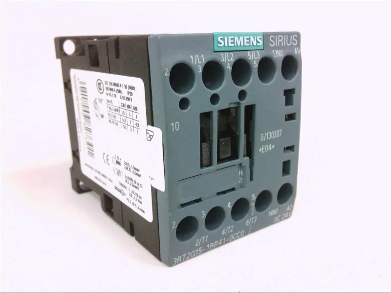
Siemens 3RT2015-1BB41-0CC0 SIRIUS Power Contactor, 24 VDC Co
Siemens SIRIUS, power contactor, 3RT2015-1BB41-0CC0, Size S00, 24 VDC coil, screw-type terminals, auxiliary switch, 45 mm width.
Specifications
| Parameter | Value |
|---|---|
| Contactor frame size | S00 |
| Parameter | Value |
|---|---|
| Rated operational current, AC-12, max. | 10 A |
| Rated operational current, AC-4 @ 400 V | 6.5 A |
| Rated value @ 400 V | 3 A |
| Rated value @ 500 V | 2 A |
| Rated value @ 690 V | 1 A |
| Rated value @ 230 V | 0.75 hp |
| Rated value @ 24 V | 10 A |
| Rated value @ 60 V | 2 A |
| Rated value @ 110 V | 1 A |
| Rated value @ 220 V | 0.3 A |
| Parameter | Value |
|---|---|
| Control supply voltage type | DC |
| Parameter | Value |
|---|---|
| Main poles | 3 |
| Main NO contacts | 3 |
| Auxiliary contact reliability | 1 faulty switching per 100 million (17 V, 1 mA) |
| Parameter | Value |
|---|---|
| Short-circuit coordination type 1, fuse | gG: 35A (690V,100kA), aM: 20A (690V,100kA), BS88: 35A (415V,80kA) |
| Short-circuit coordination type 2, fuse | gG: 20A (690V,100kA), aM: 16A (690V, 100kA), BS88: 20A (415V, 80kA) |
| Aux. switch short-circuit protection, fuse | gG: 10 A (500 V, 1 kA) |
| Parameter | Value |
|---|---|
| Main circuit connection | screw-type terminals |
| Aux. / control circuit connection | screw-type terminals |
| Conductor cross-section, solid | 0.5 ... 4 mm² |
| Conductor cross-section, solid or stranded | 2x (0.5 ... 1.5 mm²), 2x (0.75 ... 2.5 mm²), 2x 4 mm² |
| Conductor cross-section, finely stranded w/ ferrule | 2x (0.5 ... 1.5 mm²), 2x (0.75 ... 2.5 mm²) |
| Mounting method | screw and snap-on mounting onto 35 mm DIN rail according to DIN EN 60715 |
| Side-by-side mounting | Yes |
| Parameter | Value |
|---|---|
| Durability (operating cycles, typ.) | 30 000 000 |
| Durability with aux. switch block (cycles, typ.) | 10 000 000 |
| Parameter | Value |
|---|---|
| Operating temperature range | -25 ... +60 °C |
| Storage temperature range | -55 ... +80 °C |
| Installation altitude, max. | 2 000 m |
| Parameter | Value |
|---|---|
| Width | 45 mm |
| Height | 58 mm |
| Depth | 73 mm |
Product details
Frequently asked questions
What are the key ratings for 3RT2015-1BB41-0CC0?
The contactor has a 24 VDC coil, Size S00 frame, screw-type terminals, and an integrated auxiliary switch. Main contact switching frequencies: 1,000 cycles/h at AC-1, 750 cycles/h at AC-3 and AC-3e, 250 cycles/h at AC-4. Auxiliary contact DC ratings include 10 A at 24 V and 2 A at 48 V.
How do I get current pricing and availability for 3RT2015-1BB41-0CC0?
Submit an RFQ for the 3RT2015-1BB41-0CC0. Current pricing and availability are confirmed at quote time through our sourcing channels.
Will 3RT2015-1BB41-0CC0 drop into a panel specified for 3RT2015-1BW42?
Both are Size S00 Siemens SIRIUS contactors with the same 45 mm width and DIN-rail mounting, so the mechanical fit is identical. The difference is the coil voltage — 3RT2015-1BB41-0CC0 uses a 24 VDC coil, while 3RT2015-1BW42 uses a different coil voltage. Verify the coil voltage matches your control circuit before substitution.
What compliance documentation is available for 3RT2015-1BB41-0CC0?
As a Siemens SIRIUS product, the 3RT2015-1BB41-0CC0 is designed to meet IEC and UL standards typical for industrial control equipment. Specific compliance declarations (RoHS, REACH, UL, IEC) are available from Siemens upon request or through the product documentation portal.