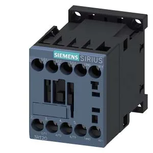
Siemens 3RT2015-1BG41 — Contactors

Siemens 3RT2015-1BG41 SIRIUS Power Contactor, Size S00, 24 V

MPN3RT2015-1BG41
Active

Siemens SIRIUS 3RT2015-1BG41 power contactor, size S00, 24 VDC coil, screw-type terminals, 10 A at 24 V, 3 A at 400 V, 45 x 58 x 73 mm.

Source DocumentedChannel stated on listing & quote
Condition PhotosReal unit photos / video on request
WhatsApp AnswersFast human replies for machine-down parts
Worldwide DispatchDHL/FedEx — transit quoted per order
Independent China distributor & sourcing agent· Listing updated Sep 2026

Specifications

3RT2015-1BG41 — Identification
ParameterValue
Contactor frame sizeS00
3RT2015-1BG41 — Ratings & Performance
ParameterValue
Rated operational current, AC-12, max.10 A
Rated operational current, AC-4 @ 400 V6.5 A
Rated value @ 400 V3 A
Rated value @ 500 V2 A
Rated value @ 690 V1 A
Rated value @ 230 V0.75 hp
Rated value @ 24 V10 A
Rated value @ 60 V2 A
Rated value @ 110 V1 A
Rated value @ 220 V0.3 A
3RT2015-1BG41 — Control & Coil
ParameterValue
Control supply voltage typeDC
3RT2015-1BG41 — Contacts & Poles
ParameterValue
Main poles3
Main NO contacts3
Auxiliary contact reliability1 faulty switching per 100 million (17 V, 1 mA)
3RT2015-1BG41 — Protection & Coordination
ParameterValue
Short-circuit coordination type 1, fusegG: 35A (690V,100kA), aM: 20A (690V,100kA), BS88: 35A (415V,80kA)
Short-circuit coordination type 2, fusegG: 20A (690V,100kA), aM: 16A (690V, 100kA), BS88: 20A (415V, 80kA)
Aux. switch short-circuit protection, fusegG: 10 A (500 V, 1 kA)
3RT2015-1BG41 — Connection & Mounting
ParameterValue
Main circuit connectionscrew-type terminals
Aux. / control circuit connectionscrew-type terminals
Conductor cross-section, solid0.5 ... 4 mm²
Conductor cross-section, solid or stranded2x (0.5 ... 1.5 mm²), 2x (0.75 ... 2.5 mm²), 2x 4 mm²
Conductor cross-section, finely stranded w/ ferrule2x (0.5 ... 1.5 mm²), 2x (0.75 ... 2.5 mm²)
Mounting methodscrew and snap-on mounting onto 35 mm DIN rail according to DIN EN 60715
Side-by-side mountingYes
3RT2015-1BG41 — Durability
ParameterValue
Durability (operating cycles, typ.)30 000 000
Durability with aux. switch block (cycles, typ.)10 000 000
3RT2015-1BG41 — Environmental
ParameterValue
Operating temperature range-25 ... +60 °C
Storage temperature range-55 ... +80 °C
Installation altitude, max.2 000 m
3RT2015-1BG41 — Mechanical
ParameterValue
Width45 mm
Height58 mm
Depth73 mm

Product details

The S00 frame is the smallest in the SIRIUS contactor family, sized for 45 mm width, 58 mm height, and 73 mm depth — it fits tightly on a 35 mm DIN rail per DIN EN 60715, with screw and snap-on mounting. The coil is 24 VDC, terminated with screw-type terminals. The main contacts accept solid or stranded wire from 0.5 to 4 mm², and up to two conductors per clamp in combinations like 2x 0.5...1.5 mm² or 2x 4 mm². This contactor is rated for a range of DC switching voltages: 10 A at 24 V, 2 A at 48 V and 60 V, 1 A at 110 V, 0.9 A at 125 V, 0.3 A at 220 V, and 3 A at 400 V. The rated value of the magnet coil is 125 V. These ratings define the maximum continuous current the contacts can carry at each voltage level — critical for sizing the contactor to the actual load voltage in the circuit. Main contacts are rated 20 to 12.

The maximum switching frequency depends on the duty class: 1,000 operations per hour for AC-1 (resistive loads), 750 per hour for AC-2 and AC-3 (motor starting and running), and 250 per hour for AC-4 (plugging, inching, or reversing). The AC-3e rating also allows 750 per hour. These numbers tell you the thermal limit of the contactor under repeated switching — exceed them and the contacts overheat, reducing life. For a motor starter cycling a conveyor every few seconds, the AC-3 limit of 750 ops/h means about one start every 4.8 seconds sustained; for reversing duty (AC-4), you need to slow down to one operation every 14.4 seconds. Mechanical service life is 30,000,000 operations typical. These are the delays between coil energization and contact closure, and between contact separation and arc extinction. For coordinating with other devices in a safety circuit or a fast PLC output, these numbers tell you the contactor's response latency.

Mounting, clearances, and environment

This matters when you're fitting it into a tight enclosure or a panel with angled DIN rails. The coil has an initial overvoltage factor of 0.8 and a full-scale overvoltage factor of 1.1. The rated voltage is 125 V.

Frequently asked questions

What clearance distances do I need around this contactor in the panel?

Minimum clearances to adjacent components are 10 mm upwards, 10 mm forwards, 10 mm downwards, and 6 mm at the side.

What wire sizes does the screw terminal accept?

Solid or stranded wire from 0.5 to 4 mm², and combinations like 2x 0.5...1.5 mm², 2x 0.75...2.5 mm², or 2x 4 mm².

MPN
3RT2015-1BG41