The coil is rated at 24 VDC nominal, with a pickup threshold of 0.8 times rated and a dropout at 1.1 times rated — meaning it pulls in reliably at about 19.2 V and drops out above 26.4 V. That's a standard control voltage for most PLC-driven panels, so you won't need a separate power supply for the coil. For the main contacts, the contactor is rated for AC-3 duty (motor switching) at a maximum of 750 switching cycles per hour, and AC-1 (resistive) at 1000 cycles per hour. If you're running a motor start/stop application, that 750 ops/h is the number to watch — it's the duty cycle that governs contact life under inductive loads. The mechanical life is typical at 30 million operations, so the contacts will wear out long before the mechanism does. The auxiliary switch is present and rated for various control voltages: 10 A at 24 V, 2 A at 48 V or 60 V, 1 A at 110 V, 0.9 A at 125 V, 0.3 A at 220 V, and 3 A at 400 V. That covers most signal-level switching you'd need for status feedback or interlocking — just match the voltage to your control circuit. The coil terminals are screw-type, so you'll need a screwdriver for termination — no spring-cage here, but that's typical for this size class and gives a solid connection in high-vibration environments.
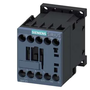
Siemens 3RT2015-1FB41-ZW96 SIRIUS Power Contactor, 24 VDC Co
Siemens SIRIUS 3RT2015-1FB41-ZW96 power contactor, size S00, 24 VDC coil, screw-type terminals, DIN rail mount.
Specifications
| Parameter | Value |
|---|---|
| Contactor frame size | S00 |
| Parameter | Value |
|---|---|
| Rated operational current, AC-12, max. | 10 A |
| Rated operational current, AC-4 @ 400 V | 6.5 A |
| Rated value @ 400 V | 3 A |
| Rated value @ 500 V | 2 A |
| Rated value @ 690 V | 1 A |
| Rated value @ 230 V | 0.75 hp |
| Rated value @ 24 V | 10 A |
| Rated value @ 60 V | 2 A |
| Rated value @ 110 V | 1 A |
| Rated value @ 220 V | 0.3 A |
| Parameter | Value |
|---|---|
| Control supply voltage type | DC |
| Parameter | Value |
|---|---|
| Main poles | 3 |
| Main NO contacts | 3 |
| Auxiliary contact reliability | 1 faulty switching per 100 million (17 V, 1 mA) |
| Parameter | Value |
|---|---|
| Short-circuit coordination type 1, fuse | gG: 35A (690V,100kA), aM: 20A (690V,100kA), BS88: 35A (415V,80kA) |
| Short-circuit coordination type 2, fuse | gG: 20A (690V,100kA), aM: 16A (690V, 100kA), BS88: 20A (415V, 80kA) |
| Aux. switch short-circuit protection, fuse | gG: 10 A (500 V, 1 kA) |
| Parameter | Value |
|---|---|
| Main circuit connection | screw-type terminals |
| Aux. / control circuit connection | screw-type terminals |
| Conductor cross-section, solid | 0.5 ... 4 mm² |
| Conductor cross-section, solid or stranded | 2x (0.5 ... 1.5 mm²), 2x (0.75 ... 2.5 mm²), 2x 4 mm² |
| Conductor cross-section, finely stranded w/ ferrule | 2x (0.5 ... 1.5 mm²), 2x (0.75 ... 2.5 mm²) |
| Mounting method | screw and snap-on mounting onto 35 mm DIN rail according to DIN EN 60715 |
| Side-by-side mounting | Yes |
| Parameter | Value |
|---|---|
| Durability (operating cycles, typ.) | 30 000 000 |
| Durability with aux. switch block (cycles, typ.) | 10 000 000 |
| Parameter | Value |
|---|---|
| Operating temperature range | -25 ... +60 °C |
| Storage temperature range | -55 ... +80 °C |
| Installation altitude, max. | 2 000 m |
| Parameter | Value |
|---|---|
| Width | 45 mm |
| Height | 58 mm |
| Depth | 73 mm |
Product details
Frequently asked questions
What are the key ratings for this contactor?
It's a size S00 power contactor with a 24 VDC coil, rated for AC-3 motor switching at up to 750 cycles per hour. The auxiliary switch handles up to 10 A at 24 VDC, and the main contacts have a mechanical life of 30 million operations.
What wire sizes does it accept?
It accepts solid or stranded wire from 0.5 to 4 mm², and can take two conductors per terminal for daisy-chaining.
What are the mounting requirements?
It mounts on a 35 mm DIN rail per DIN EN 60715 with screw and snap-on fastening. Clearances needed are 10 mm up, down, and forward, and 6 mm at the sides.
Will this drop into a panel designed for a 3RT2015-1AT62?
Both are size S00 Siemens SIRIUS contactors sharing the same footprint and DIN-rail mounting, so it will drop into the same panel slot without rewiring — just verify the coil voltage (24 VDC on this one) matches your control circuit.