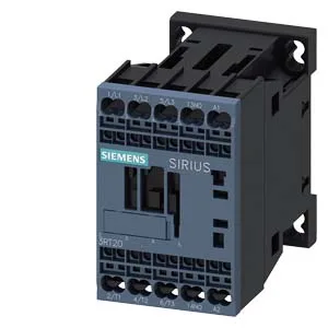
The contactor mounts via screw or snap-on onto a standard 35 mm DIN rail per DIN EN 60715, and the mounting position allows ±180° rotation on a vertical surface plus ±22.5° tilt forward/backward — useful when fitting into tight enclosures.
The 10 A rating at 24 V is the DC-1 resistive load current the main contacts can handle at that coil voltage. For inductive DC loads (DC-3/DC-5), the rating drops significantly — 2 A at 48 V, 1 A at 110 V, 0.3 A at 220 V — so match your load type and voltage to the correct column. Switching frequency varies by duty: up to 1000 operations per hour at AC-1 (resistive), 750/h at AC-3 (motor start/run), and 250/h at AC-4 (plugging/inching). The AC-3e rating also sits at 750/h. If your application cycles faster than these limits, the contactor will overheat — the thermal limit is the package, not the coil.
Strip length is not stated here, but spring terminals typically need 8-10 mm — verify against the datasheet before terminating. An auxiliary switch is built in, with contact ratings listed for various voltages: 10 A at 24 V, 2 A at 48 V, 0.9 A at 125 V, 0.3 A at 230 V. These are the switching capacities for the aux contacts — don't exceed them even if the main contacts are lightly loaded.
For a BOM freeze or second-source gate, the closest functional peer in the same SIRIUS family is the 3RT2026-1AG20, which is a larger frame size. The 3RT2015-2AK61 will not drop into a panel wired for the 3RT2026-1AG20 without rewiring — the footprint and terminal layout differ. Verify your panel's cutout and wiring before assuming interchangeability.