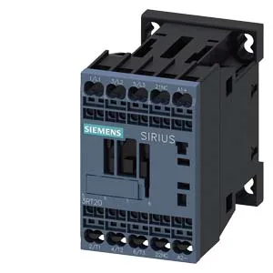
SIRIUS S00 power contactor with 24 VDC coil and spring terminals
It carries a 24 VDC coil rated at 0.8 A initial inrush and 1.1 A holding current at full-scale, with spring-type terminals accepting 0.5 to 4 mm² solid or stranded wire (2x per clamp). The 24 VDC coil holds at nominal voltage and drops out below the pick-up threshold; the DC arcing time of 7 to 13 ms on the main contacts means the arc extinguishes quickly, reducing contact wear during DC switching events.
Ratings and switching capability
The auxiliary contacts are rated for switching at various voltages: 10 A at 24 VDC, 2 A at 48 V and 60 VDC, 1 A at 110 VDC, 0.9 A at 125 VDC, 0.3 A at 220 VDC, and 3 A at 400 VAC. The motor horsepower rating at 230 V is 0.75 hp. These ratings define the maximum switching capacity for the auxiliary circuit — important when driving small relays, pilot lights, or PLC inputs in the same panel. Mechanical switching frequency varies by duty class: up to 1,000 operations per hour at AC-1 (resistive), 750/h at AC-2 and AC-3 (motor starting/running), and 250/h at AC-4 (plugging/inching). The AC-3e rating matches the AC-3 figure at 750/h. The main contacts are configured as 20... 12 (normally open / normally closed) per the evidence, and an auxiliary switch is included.
These are minimum air gaps for heat dissipation and arc flash containment — a panel layout that crowds the contactor against other components risks derating or nuisance tripping. Dimensions are 73 mm depth, 45 mm width, and 70 mm height. No special tools needed beyond a screwdriver for the spring release.