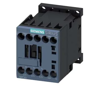
The Siemens 3RT2016-1AB01-ZW97 is a SIRIUS-branded power contactor in the size S00 frame, fitted with a 24 VDC magnet coil terminated to screw-type terminals. The contactor carries an integrated auxiliary switch, which simplifies wiring for status feedback or interlocking without a separate add-on block. The auxiliary contact ratings span from 10 A at 24 V rated value down to 0.2 A at 440 V rated value, covering both low-voltage PLC signals and higher-voltage indication circuits.
Duty-cycle and switching frequency limits
Maximum switching frequency depends on the duty class: AC-1 (resistive loads) allows up to 1 000 1/h, while AC-2 and AC-3 (motor starting and running) are limited to 750 1/h. The AC-3e rating also caps at 750 1/h. For AC-4 duty (plugging, inching), the rate drops to 250 1/h. These limits govern thermal rise in the coil and main contacts — exceeding them accelerates wear or causes nuisance tripping. Arcing time is specified at 10 to 15 ms at AC, with a make time of 4 to 15 ms at AC. These values matter for coordination with upstream fuses or circuit breakers — the let-through energy during a fault must be within the interrupting rating of the protective device.
Wiring and clearance dimensions
Terminals accept solid or stranded conductors from 0.5 to 4 mm², with dual-wire capability: 2x (0.5 to 1.5 mm²), 2x (0.75 to 2.5 mm²), or 2x 4 mm². This covers common control and power wiring sizes without needing ferrule adapters. Envelope dimensions are 73 mm depth, 45 mm width, and 58 mm height. These spacings ensure adequate ventilation and arc flash containment within the panel.