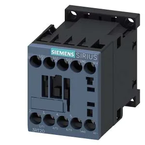
The Siemens 3RT2016-1VB41 is a SIRIUS coupling contactor in size S00, designed for switching loads where the control circuit and power circuit need galvanic separation — common in PLC-to-motor isolation or signal-level interposing between a safety relay and a motor starter. The 24 V DC coil pulls in at 85 % of rated voltage and drops out at the same threshold, which means it holds reliably down to about 20.4 V and releases cleanly below that — no chatter on a sagging 24 V bus. The contactor mounts via screw fixing or snaps onto a 35 mm DIN rail per DIN EN 60715, and the mounting position allows ±180° rotation on a vertical surface plus ±22.5° tilt forward or backward — useful when the panel layout forces an odd orientation.
Switching capacity — what the DC and AC ratings mean for your load
The DC breaking capacity follows the voltage curve: 10 A at 24 V, dropping to 2 A at 48 V and 60 V, then 1 A at 110 V, 0.9 A at 125 V, 0.3 A at 220 V, and 3 A at 400 V. That steep derating is typical for DC switching — the arc doesn't self-extinguish at zero-crossing the way AC does. For a 24 V DC solenoid valve bank or a small DC motor brake, the 10 A rating gives headroom; at higher DC voltages the contactor is really only good for signal-level loads or very low-current pilot duty. On AC motor duty, the contactor is rated 1 hp at 230 V, which corresponds to roughly 5 A in AC-3 (starting and stopping a squirrel-cage motor under load). The maximum operating rate is 750 cycles per hour in AC-3 and AC-3e, and 250 cycles per hour in AC-4 (plugging or inching). If your application requires frequent jogging or reversing, stay within the AC-4 rate — exceeding it overheats the arc chamber and accelerates contact wear.
Termination and wiring constraints
For multi-conductor runs, the terminal accepts 2 × (0.5 to 1.5 mm²), 2 × (0.75 to 2.5 mm²), or 2 × 4 mm². The main contact terminals are sized for AWG 20 to 12. That means you can land a single 12 AWG THHN on the line side and daisy-chain a 14 AWG to the overload relay without pigtails — the dual-wire capacity is there.
Environmental limits and mechanical life
Electrical life depends on the switching category and current; at rated AC-3 current you'll get far fewer cycles before contact erosion, but the mechanical rating tells you the solenoid and spring assembly won't fatigue prematurely.