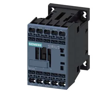
Siemens 3RT2016-2AP62 — Contactors

Siemens 3RT2016-2AP62 SIRIUS Power Contactor, Size S00, 24 V

MPN3RT2016-2AP62
Active

Siemens SIRIUS, Power contactor, 3RT2016-2AP62, Size S00, 24 V DC coil, spring-type terminals, 10 A at 24 V rated value, screw and snap-on mounting onto 35 mm DIN rail.

Source DocumentedChannel stated on listing & quote
Condition PhotosReal unit photos / video on request
WhatsApp AnswersFast human replies for machine-down parts
Worldwide DispatchDHL/FedEx — transit quoted per order
Independent China distributor & sourcing agent· Listing updated Sep 2026

Specifications

3RT2016-2AP62 — Identification
ParameterValue
Contactor frame sizeS00
3RT2016-2AP62 — Ratings & Performance
ParameterValue
Rated operational current, AC-12, max.10 A
Rated operational current, AC-4 @ 400 V8.5 A
Rated value @ 400 V3 A
Rated value @ 500 V2 A
Rated value @ 690 V1 A
Rated value @ 230 V1 hp
Rated value @ 24 V10 A
Rated value @ 60 V2 A
Rated value @ 110 V1 A
Rated value @ 220 V0.3 A
3RT2016-2AP62 — Control & Coil
ParameterValue
Control supply voltage typeAC
Rated value @ 50 Hz0.24
Rated value @ 50 Hz220 V
3RT2016-2AP62 — Contacts & Poles
ParameterValue
Main poles3
Main NO contacts3
Auxiliary contact reliability1 faulty switching per 100 million (17 V, 1 mA)
3RT2016-2AP62 — Protection & Coordination
ParameterValue
Short-circuit coordination type 1, fusegG: 35A (690V,100kA), aM: 20A (690V,100kA), BS88: 35A (415V,80kA)
Short-circuit coordination type 2, fusegG: 20A (690V,100kA), aM: 16A (690V, 100kA), BS88: 20A (415V, 80kA)
Aux. switch short-circuit protection, fusegG: 10 A (500 V, 1 kA)
3RT2016-2AP62 — Connection & Mounting
ParameterValue
Main circuit connectionspring-loaded terminals
Aux. / control circuit connectionspring-loaded terminals
Conductor cross-section, solid0.5 ... 4 mm²
Conductor cross-section, solid or stranded2x (0,5 ... 4 mm²)
Conductor cross-section, finely stranded w/ ferrule2x (0.5 ... 2.5 mm²)
Mounting methodscrew and snap-on mounting onto 35 mm DIN rail according to DIN EN 60715
Side-by-side mountingYes
3RT2016-2AP62 — Durability
ParameterValue
Durability (operating cycles, typ.)30 000 000
Durability with aux. switch block (cycles, typ.)10 000 000
3RT2016-2AP62 — Environmental
ParameterValue
Operating temperature range-25 ... +60 °C
Storage temperature range-55 ... +80 °C
Installation altitude, max.2 000 m
3RT2016-2AP62 — Mechanical
ParameterValue
Width45 mm
Height70 mm
Depth73 mm
3RT2016-2AP62 — Specifications
ParameterValue
At AC4 ... 15 ms

Product details

Mounting is screw or snap-on onto 35 mm DIN rail per DIN EN 60715, and the mounting position allows ±180° rotation on a vertical surface plus ±22.5° tilt forward/backward, so it fits tight enclosures without a special bracket. Physical footprint is 45 mm wide, 70 mm high, 73 mm deep — the depth matters for gland-plate clearance if you're panel-building to a shallow backplate.

Rated operational current at 24 V DC is 10 A, dropping to 3 A at 400 V DC and 0.2 A at 440 V DC — the inductive DC load curve is steep, so don't assume the 24 V figure holds at higher voltages. For AC-3 motor switching, the maximum operating frequency is 750 cycles per hour; AC-4 (inching/plugging) drops to 250 cycles per hour. If your application needs frequent jogging, that 250 c/h limit is the hard stop — the contactor's mechanical life of 30 million operations won't be the constraint, the arc-erosion rate at AC-4 will be.

Wire termination and environmental limits

Spring-type terminals accept solid or stranded wire from 0.5 to 4 mm², and up to 2x (0.5 to 4 mm²) per clamp — useful for daisy-chaining control wiring without a separate terminal block.

Frequently asked questions

What are the key dimensions for panel layout?

Width 45 mm, height 70 mm, depth 73 mm. Required clearances: 10 mm upward, 10 mm downward, 10 mm forward, 6 mm to the side.

What wire sizes does the spring terminal accept?

Solid or stranded 0.5 to 4 mm² per clamp, and up to 2x (0.5 to 4 mm²) when paralleling two conductors.

MPN
3RT2016-2AP62