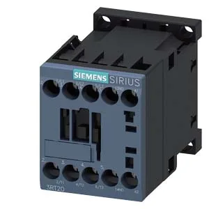
Integrator note — SIRIUS 3RT2017-1BE42
The 24 VDC coil pulls in reliably; the screw-type terminals on the magnet coil accept solid or stranded wire from 0.5 to 4 mm², with dual-wire entries for 2x (0.5...1.5 mm²), 2x (0.75...2.5 mm²), or 2x 4 mm². Rated at 10 A at 24 V for DC switching, it also carries 2 A at 48 V and 60 V, 1 A at 110 V, 0.9 A at 125 V, and 0.3 A at 220 V — so the DC load curve drops fast above 24 V; size the load accordingly.
Duty-cycle and switching frequency
Switching frequency depends on the duty category: AC-1 (resistive) allows up to 1,000 operations per hour, AC-2 and AC-3 (motor starting/running) cap at 750 ops/h, AC-3e (enhanced motor) also 750 ops/h, and AC-4 (plugging/inching) drops to 250 ops/h. The main contact rating range is 20 to 12 (likely a code for current range in amps depending on duty), and the contactor carries an auxiliary switch for feedback or status signaling. Mechanical life typical is 30 million operations — a solid figure for a Size S00 frame.
The contactor is rated for use in standard industrial environments; no IP rating is listed, so it expects panel protection from dust and moisture.
Panel integration checklist
DIN rail: 35 mm per DIN EN 60715, screw or snap-on. Width 45 mm, depth 73 mm, height 58 mm. Leave 10 mm clearance above, below, and forward; 6 mm at sides for heat dissipation and wiring access. Wiring: screw-type terminals on coil and main contacts. Solid/stranded 0.5...4 mm² single wire, or dual 2x (0.5...1.5 mm²), 2x (0.75...2.5 mm²), 2x 4 mm². Torque not specified in evidence — use standard M3.5 screw terminal torque (0.8-1.2 Nm) typical for this class.