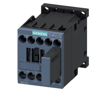
The 3RT2017-1WB42: It mounts via screw and snap-on onto 35 mm DIN rail per DIN EN 60715, with a width of 45 mm, height 58 mm, and depth 117 mm.
The main contacts are rated for DC switching at several voltages: 10 A at 24 V, 2 A at 48 V, 2 A at 60 V, 1 A at 110 V, 0.9 A at 125 V, 0.3 A at 220 V, and 3 A at 400 V. These are the resistive-load DC ratings per the datasheet — if your load is inductive, you'll need to derate or add a free-wheeling diode across the coil. For AC motor loads, the contactor is rated 2 hp at 230 V. The maximum switching frequency depends on the duty class: 1,000 cycles/hour for AC-1 (resistive), 750 cycles/hour for AC-2 and AC-3 (motor starting/running), and 250 cycles/hour for AC-4 (plugging/inching).
Termination and wiring notes
The magnet coil uses screw-type terminals. Main contacts accept solid or stranded wire from 0.5 to 4 mm², or two conductors per terminal: 2x (0.5 to 1.5 mm²), 2x (0.75 to 2.5 mm²), or 2x 4 mm². These are the minimum air gaps to maintain rated isolation — factor them into your panel layout.
Environmental and service life
The typical mechanical service life is 30,000,000 operations.