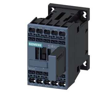
The 3RT2017-2QB41: The contactor mounts via screw and snap-on onto 35 mm DIN rail per DIN EN 60715, and its spring-type terminals accept solid or stranded wire from 0.5 to 4 mm², including 2x (0.5 to 4 mm²) per clamp. That means it integrates directly into a standard panel without special adapters or crimp tools beyond a ferrule set.
The coil is rated 24 VDC with a pickup of 0.7 x rated value and a dropout of 1.25 x full-scale value, so it pulls in reliably at about 17 V and drops out at about 30 V. This gives a clean switching threshold for PLC or relay outputs driving the coil. The main contacts carry 10 A at 24 VDC, 2 A at 48 V and 60 V, 1 A at 110 V, 0.9 A at 125 V, and 0.3 A at 220 V. The drop at higher voltages reflects DC arc extinction limits; for a 48 V or 60 V circuit, size up if your load exceeds 2 A. Mechanical life is typical 30 million operations, and the maximum switching frequency ranges from 1 000 cycles per hour at AC-1 (resistive) down to 250 at AC-4 (plugging/inching). For a coupling contactor that may cycle with every machine start, the AC-3 and AC-3e rating of 750 cycles per hour is the realistic limit for motor switching.
Mounting and spacing
The contactor measures 45 mm wide, 70 mm high, and 121 mm deep. Required clearances are 10 mm upward, 10 mm forward, 10 mm downward, and 6 mm at the side — tight enough for dense panel layouts but check the 121 mm depth against enclosure depth if mounting on a back panel with a shallow door.