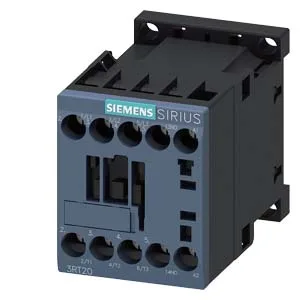
Mounting is flexible: screw-fix or snap onto a 35 mm DIN rail per DIN EN 60715, and the mounting position allows ±180° rotation on a vertical surface plus ±22.5° tilt forward or backward. That gives the panel builder options when laying out a dense enclosure.
The coil is rated 24 VDC, pulling 10 A at that voltage. That's the inrush to pick the magnet; the holding current is lower. For DC-13 switching (solenoid loads, clutches, brakes), the contactor is rated 10 A at 24 V, 2 A at 48 V and 60 V, 1 A at 110 V, 0.9 A at 125 V, and 0.3 A at 220 V. These DC-13 ratings are the ones that govern real inductive DC loads — don't size by the AC ratings alone. Mechanical life is typical 30 million operations. Electrical endurance depends on the duty cycle: at AC-1 (resistive) it's rated 1,000 operations per hour max; at AC-3 (squirrel-cage motors) and AC-3e it's 750 per hour; at AC-4 (plugging, inching) it drops to 250 per hour. These numbers let you calculate whether the contactor survives the cycle count in a high-speed pick-and-place or conveyor application. Wire capacity covers solid and stranded from 0.5 to 4 mm², with dual-wire terminations possible: 2x (0.5 to 1.5 mm²), 2x (0.75 to 2.5 mm²), or 2x 4 mm². The screw-type terminals are straightforward for panel wiring — no special tooling needed.