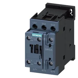
The S0 frame is the mid-size in the SIRIUS contactor family — sized for motor loads up to the AC-3 rating of the main contacts (rated for 16 A at 400 V, with a 1 hp rating at 230 V).
Integration & Wiring
Auxiliary contact terminals accept 2x (0.5 to 1.5 mm²) or 2x (0.75 to 2.5 mm²) solid or stranded. The auxiliary switch is included — verify the contact configuration against your control scheme. These govern panel layout for arc-flash and heat dissipation — the 97 mm depth and 85 mm height fit standard S0 contactor footprints. The coil draws 0.25 A at 50 Hz and 0.28 A at 60 Hz. Arcing time is 10 ms. Switching frequency is 1,000 operations per hour for AC-1, AC-2, AC-3, and AC-3e duty; 300 ops/h for AC-4 (plugging/reversing).
The auxiliary contacts carry rated operational currents across common control voltages: 10 A at 24 V, 2 A at 48 V and 60 V, 1 A at 110 V, 0.9 A at 125 V, 0.3 A at 220 V, 3 A at 400 V, and 0.6 A at 440 V. These are the values for the auxiliary switch block — use them to confirm compatibility with your PLC outputs or relay coils.