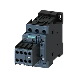
The preferred mounting position is standing on a horizontal surface. The Size S0 footprint is compact enough for dense panel layouts.
Wiring and terminal capacity
For auxiliary circuits, the terminal accepts 2x (0.5 to 1.5 mm²) or 2x (0.75 to 2.5 mm²). The coil connection uses screw-type terminals. This covers most panel wiring up to 10 mm² without needing adapters.
Switching ratings and operating conditions
Rated for 10 A at 24 VDC, with derated values at higher voltages: 2 A at 48 VDC, 2 A at 60 VDC, 1 A at 110 VDC, 0.9 A at 125 VDC, 0.3 A at 220 VDC, and 3 A at 400 VDC. The contactor is rated for 1 hp at 230 V. Maximum switching frequency is 1,000 cycles per hour for AC-1, AC-2, AC-3, and AC-3e duty, and 300 cycles per hour for AC-4 duty.