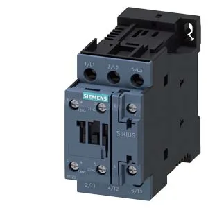
The Size S0 footprint — 45 mm wide, 85 mm high, 107 mm deep — fits standard panel layouts where the contactor sits between a motor-protective breaker and an overload relay on the DIN rail. The DC coil rating at 52 V is the operating voltage, not the pickup voltage; the initial pickup is 0.8 of rated value, so the coil pulls in reliably at about 42 VDC and holds at the full 52 V. Switching frequency tops out at 1 000 cycles per hour for AC-1, AC-2, AC-3, and AC-3e duty, dropping to 300 cycles per hour for AC-4 — the heavy inrush of plugging or inching. That 300-cycle limit is the real constraint for applications with frequent reversing or jogging. DC switching ratings are load-dependent: 10 A at 24 V, 2 A at 48 V and 60 V, 1 A at 110 V, 0.9 A at 125 V, 0.3 A at 220 V, and 3 A at 400 V. These are the currents the main contacts can break in DC circuits — the voltage step matters because DC arcs don't self-extinguish at zero-crossing the way AC does. For a 24 VDC solenoid or brake, the 10 A rating gives headroom; at 110 VDC the contactor is limited to 1 A.
The 107 mm depth matters when the gland plate or enclosure door clearance is tight — measure the rail-to-door depth before committing the panel layout. Wire range accepts solid or stranded conductors from 1 to 10 mm², and two-wire combinations of 2x (0.5... 1.5 mm²) or 2x (0.75... 2.5 mm²). The screw terminals on the magnet coil match the main contact termination style, so no mixed tooling on the line.