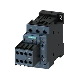
Siemens 3RT2023-1XF40-0LA2 — Contactors

Siemens 3RT2023-1XF40-0LA2 SIRIUS Power Contactor, 110 VDC C

MPN3RT2023-1XF40-0LA2
Active

Siemens SIRIUS power contactor, 3RT2023-1XF40-0LA2, size S0, 110 VDC coil, screw-type terminals, 45 mm width, screw and snap-on 35 mm DIN rail mounting.

Source DocumentedChannel stated on listing & quote
Condition PhotosReal unit photos / video on request
WhatsApp AnswersFast human replies for machine-down parts
Worldwide DispatchDHL/FedEx — transit quoted per order
Independent China distributor & sourcing agent· Listing updated Sep 2026

Specifications

3RT2023-1XF40-0LA2 — Identification
ParameterValue
Contactor frame sizeS0
3RT2023-1XF40-0LA2 — Ratings & Performance
ParameterValue
Rated operational current, AC-12, max.10 A
Rated operational current, AC-4 @ 400 V8.5 A
Rated value @ 400 V3 A
Rated value @ 500 V2 A
Rated value @ 690 V1 A
Rated value @ 230 V1 hp
Rated value @ 24 V10 A
Rated value @ 60 V2 A
Rated value @ 110 V1 A
Rated value @ 220 V0.3 A
3RT2023-1XF40-0LA2 — Control & Coil
ParameterValue
Control supply voltage typeDC
3RT2023-1XF40-0LA2 — Contacts & Poles
ParameterValue
Main poles3
Main NO contacts3
3RT2023-1XF40-0LA2 — Protection & Coordination
ParameterValue
Short-circuit coordination type 1, fusegG: 63A (690V,100kA), aM: 32A (690V,100kA), BS88: 63A (415V,80kA)
Short-circuit coordination type 2, fusegG: 25A (690V,100kA), aM: 20A (690V,100kA), BS88: 25A (415V,80kA)
Aux. switch short-circuit protection, fusegG: 10 A (500 V, 1 kA)
3RT2023-1XF40-0LA2 — Connection & Mounting
ParameterValue
Main circuit connectionscrew-type terminals
Aux. / control circuit connectionscrew-type terminals
Conductor cross-section, solid2x (1 ... 2.5 mm²), 2x (2.5 ... 10 mm²)
Conductor cross-section, solid or stranded2x (0.5 ... 1.5 mm²), 2x (0.75 ... 2.5 mm²)
Conductor cross-section, finely stranded w/ ferrule2x (0.5 ... 1.5 mm²), 2x (0.75 ... 2.5 mm²)
Mounting methodscrew and snap-on mounting onto 35 mm DIN rail according to DIN EN 60715
Side-by-side mountingYes
3RT2023-1XF40-0LA2 — Durability
ParameterValue
Durability (operating cycles, typ.)10 000 000
Durability with aux. switch block (cycles, typ.)10 000 000
3RT2023-1XF40-0LA2 — Environmental
ParameterValue
Operating temperature range-40 ... +70 °C
Storage temperature range-55 ... +80 °C
Installation altitude, max.2 000 m
3RT2023-1XF40-0LA2 — Mechanical
ParameterValue
Width45 mm
Height85 mm
Depth107 mm

Product details

It is rated for a 110 VDC coil supply, with screw-type terminals for the magnet coil. The contactor mounts via screw or snap-on onto 35 mm DIN rail per DIN EN 60715, and its mounting position allows +/-180° rotation on a vertical surface, plus +/-22.5° tilt forward and backward.

The 110 VDC coil draws a 15 A inrush peak, so the control transformer or DC supply must handle that surge without droop. The coil hold-in is rated for DC, with a drop-out time of 30 to 50 ms at DC — this matters for sequencing logic where you need predictable off-delay. Wire termination accepts solid conductors: 2x (1 to 2.5 mm²) and 2x (2.5 to 10 mm²) for the main contacts, and 2x (0.5 to 1.5 mm²) or 2x (0.75 to 2.5 mm²) for auxiliary circuits. This covers standard control wiring up to 10 mm² for power feeds.

This fits standard S0-size contactor spacing in most enclosures. Mechanical switching frequency: 1,000 operations per hour for AC-1, AC-2, AC-3, and AC-3e duty; 300 operations per hour for AC-4. The arcing time is 10 ms, consistent with DC coil contactors.

Frequently asked questions

What are the key dimensions for panel layout?

Width is 45 mm, depth is 107 mm, and height is 85 mm. Clearance required: 10 mm upward, 10 mm forward, 10 mm downward, and 6 mm at the side.

What wire sizes does the contactor accept?

Main contacts accept solid conductors: 2x (1 to 2.5 mm²) and 2x (2.5 to 10 mm²). Auxiliary contacts accept 2x (0.5 to 1.5 mm²) or 2x (0.75 to 2.5 mm²) solid or stranded.

What is the coil voltage and type?

The coil is rated for 110 V DC, with screw-type terminals. Inrush peak is 15 A.

MPN
3RT2023-1XF40-0LA2