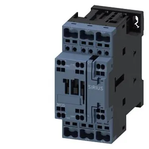
It mounts via screw or snap-on onto 35 mm DIN rail per DIN EN 60715, with a mounting position flexibility of ±180° rotation and ±22.5° tilt on a vertical surface — useful when panel layout is tight. The coil connection uses spring-type terminals, and the main circuit wiring accepts solid or stranded conductors from 1 to 10 mm², with auxiliary contacts accepting 2x (0.5 to 2.5 mm²). Physical footprint is 45 mm wide, 102 mm high, and 97 mm deep — standard S0 envelope that drops into existing rail layouts without re-spacing.
The AC-4 rating drops to 300 ops/h — that's the inching or plugging duty cycle, so if your application requires frequent reversing or jogging, factor that lower limit into your mechanical life expectation. Switching capacity varies by voltage: at 24 V rated value it carries 10 A, at 400 V rated value it carries 3 A, and at 480 V rated value it carries 7.6 A. The 480 V figure is notable — higher than the 400 V rating because of the different load curve (likely resistive or specific motor HP rating at that voltage). For DC switching, the 24 V rated value is 10 A, dropping to 0.3 A at 220 V rated value. Arcing time is specified at 10 ms, with a switching interval at AC of 4 to 16 ms. These numbers matter when coordinating with upstream protection — the contactor clears fast enough to let a typical motor circuit protector (MCP) handle the fault without welding the main contacts.
Lifecycle and compliance posture
The auxiliary switch is included as standard.
These are the minimum air gaps for heat dissipation and arc containment — respect them in dense panels. The spring-type terminals on the coil mean no screw torque to verify, but strip length and ferrule quality matter more than with screw clamps. For auxiliary wiring, 2x (0.5 to 2.5 mm²).