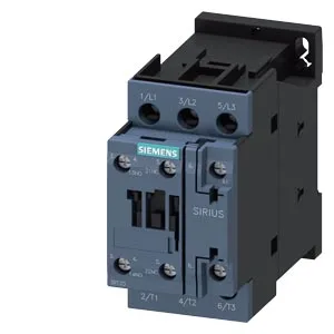
The coil is rated for 24 VDC, and at that voltage the auxiliary contacts switch 10 A — the figure that governs your load-side wiring, not the coil draw. It mounts via screw and snap-on onto 35 mm DIN rail per DIN EN 60715, with a width of 45 mm and depth of 107 mm — that 45 mm footprint is the S0 standard, so it drops into any panel ganged for S0 contactors without re-spacing the gland plate. The 10 mm clearance to live parts above, below, and forward is the minimum for the S0 air gap — verify your enclosure layout against those numbers before committing the BOM.
Switching frequency and duty cycles
Rated at 1,000 switching cycles per hour for AC-1 (resistive) and AC-3 (motor starting) duty, and 300/h for AC-4 (plugging/inching). The AC-3 rate covers most conveyor and pump starts; the AC-4 limit matters if the contactor sees reversing or jogging cycles — stay under 300/h there. Electrical life depends on the switched load; the AC-3 rating is your real-world wear reference.
Panel integration and mounting notes
Auxiliary contacts are present (Auxiliary Switch: Yes). The magnet coil connection is a ring cable lug — no quick-connect; factor in the lug crimp tool and ring terminal size for your wiring schedule.