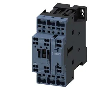
SIRIUS S0 contactor with spring-type coil terminals
The 3RT2025-2BB40-0CC0: The spring-type coil connection means no screw tightening on the coil leads — push the stripped wire in and the cage clamps it. This saves a few seconds per termination on the line and eliminates the risk of a loose screw on a coil circuit that sees vibration.
Mounting position and clearance envelope
This matters when you're shoehorning it into a crowded panel — you aren't locked to one orientation. These are the minimum air gaps to adjacent metalwork or other devices for proper arc quenching and heat dissipation. If you crowd it tighter than 6 mm side-to-side, you risk arc flashover between adjacent contactors under fault. Physical envelope: 102 mm high, 45 mm wide, 107 mm deep. The depth dimension is the critical one for shallow back-panel enclosures — 107 mm means it clears most 120 mm deep enclosures with a few mm to spare for wiring behind the contactor.
Wire termination and conductor sizing
This covers the common control wiring range — 1.5 mm² for power circuits and 0.75 mm² or 1.0 mm² for signal wiring. The main contact wire range of 18 to 8 AWG means you can land a 10 mm² (8 AWG) feeder on the line side and a 4 mm² (12 AWG) motor lead on the load side without needing a reducer or pigtail.
Auxiliary contact ratings and switching capability
These are the make-and-break ratings for the auxiliary contacts — not the continuous carry current. If you're switching a 24 VDC PLC input, the 10 A rating is generous; but at 125 VDC the 0.9 A limit means a small relay coil is fine, a large contactor coil may exceed it. Motor horsepower rating is 3 hp at 230 V. This is the AC-3 motor switching capability — the contactor is sized for a 3 hp, 230 V single-phase or three-phase motor load. For a 3 hp motor drawing roughly 9-10 A at 230 V, the contactor's thermal capacity is adequate with margin.
Switching frequency and timing
Maximum switching rate is 1,000 operations per hour for AC-1, AC-2, AC-3, and AC-3e duty. For AC-4 duty (plugging, inching, reversing) the rate drops to 300 operations per hour. Arcing time is 10 ms, and the DC operating time (coil pull-in) is 15 to 18 ms. The arcing time is the period the arc sustains between opening contacts — 10 ms is typical for a contactor this size and means the arc extinguishes within one half-cycle at 50 Hz. The coil pull-in time of 15-18 ms means the main contacts close about 15 ms after the coil is energized.
Temperature limits and mechanical endurance
The -25 °C lower limit means the contactor is rated for unheated enclosures in temperate climates but not for deep-freeze or arctic outdoor installations without enclosure heating. This is the mechanical endurance without electrical load — the contactor's armature and spring assembly is rated for 10 million cycles before mechanical wear becomes a concern. Under full AC-3 load, electrical life will be lower, typically 1-2 million operations.
Lifecycle status and sourcing
Sourced to order against BOM quantities through independent distribution. No stock-holding claim — each RFQ is handled individually.