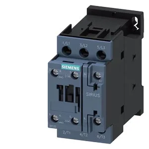
The magnet coil is screw-type terminals rated at 24 VDC, with a holding current draw of 0.25 A at 50 Hz and 0.28 A at 60 Hz — relevant for power supply budgeting in multi-contactor panels. Mechanical life is typical 10,000,000 operations, with maximum switching frequency varying by duty: 1,000 cycles/h at AC-1 (resistive), 750 cycles/h at AC-2 and AC-3 (motor starting/running), and 250 cycles/h at AC-4 (plugging/inching). The AC-3e rating also permits 750 cycles/h.
Dimensions, Clearances, and Wiring
Dimensions: 85 mm height, 45 mm width, 97 mm depth. The 45 mm width occupies one standard 45 mm module on a DIN rail, leaving adjacent space for auxiliary contact blocks or other devices. These are minimums; panel layout should respect them to avoid derating. Auxiliary contact terminals accept 2x (0.5 to 1.5 mm²) or 2x (0.75 to 2.5 mm²) solid or stranded. Screw torque for main contacts is 16 to 8 Nm.
Auxiliary Contact Ratings and Arcing
Rated contact currents for the auxiliary circuit at various voltages: 10 A at 24 V, 2 A at 48 V, 2 A at 60 V, 1 A at 110 V, 0.9 A at 125 V, 0.3 A at 220 V, 3 A at 400 V, 0.6 A at 440 V. These are the make/break capacities for the auxiliary contacts, not the main power path. Arcing time is 10 to 10 ms (a fixed value of 10 ms) at AC. The main contact arc extinction is within this window, which informs coordination with upstream protective devices. Motor horsepower rating: 3 hp at 230 V, indicating suitability for small motor loads in North American single-phase or three-phase applications at that voltage.
Storage temperature: -55 to +80 °C. The storage range exceeds the operating range — relevant for warehousing and shipping conditions, not running performance. This allows installation in non-standard orientations without derating, per the datasheet.