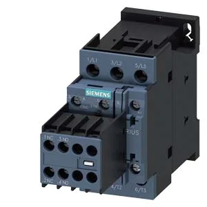
Screw-type terminals on the coil and main contacts, no built-in auxiliary switch block, so you'll add a separate auxiliary contactor or relay for feedback or status signals. Mounts via screw or snap-on onto 35 mm DIN rail per EN 60715, with ±180° rotation on a vertical surface and ±22.5° tilt forward/backward — flexible for tight enclosures where the rail orientation isn't ideal.
Switching capacity and duty cycle — the numbers that matter
Main contacts rated for 16 A at AC-3 (motor duty) and 8 A at AC-4 (inching/plugging). That AC-3 rating is the one you size against: it handles the motor start inrush and breaks the running current. The contactor can cycle at 750 operations per hour under AC-3 or AC-2 duty, and 1 000 ops/h under AC-1 (resistive). For AC-4 (high-stress reversing or jogging), drop to 250 ops/h — the arc energy at break limits the mechanical life at that duty. Coil draws 0.25 A at 50 Hz, 0.28 A at 60 Hz — factor that into your 24 VDC control transformer sizing.
Wiring and panel fit
For control wiring, it takes dual conductors: 2x 0.5–1.5 mm² or 2x 0.75–2.5 mm² — handy for daisy-chaining the coil supply to multiple contactors without extra terminal blocks. Dimensions: 85 mm high, 45 mm wide, 141 mm deep. The 45 mm width is one standard 9 mm module pitch (5 modules wide) — plan your DIN rail layout accordingly. That 6 mm side gap is tight; if you're packing contactors side-by-side, verify heat dissipation for continuous high-duty cycles.