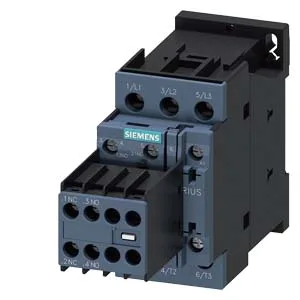
The 3RT2026-1AP04-ZX95: The 21 A rating at 480 V defines the maximum continuous current the main contacts can carry at that voltage — use it to size the contactor for a motor full-load current below that threshold, with headroom for inrush. The 3 hp at 230 V rating gives a direct motor-size match for single-phase or line-to-line loads. At 24 V, the contactor switches 6 A, which covers control transformer or resistive loads on the low-voltage side. The solid and stranded wire range of 1 to 10 mm² accepts standard power conductors up to 6 AWG — no need for ferrule adapters on stranded runs.
The 45 mm width and 85 mm height with 141 mm depth fit a standard S0 footprint — plan for 45 mm per contactor on the DIN rail, plus 6 mm side clearance to adjacent devices for airflow and wiring access.
Switching Performance and Mechanical Life
Maximum switching frequency varies by duty: 1,000 operations per hour at AC-1 (resistive), 750/h at AC-2 and AC-3 (motor starting/running), and 250/h at AC-4 (plugging/inching) (–,). For main contact torque, the tightening range is 16 to 8 Nm, though this appears to be a data entry range; standard practice for S0 terminals is typically lower — verify against the nameplate or manual before torquing.