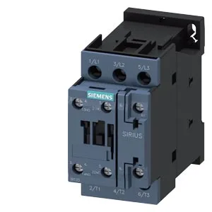
The headline numbers: 10 A switching current at 24 V, 3 hp at 230 V, 3 A at 400 V. Those are the currents it can make and break under those voltages — the 24 V figure matters for control circuits or low-voltage motor branches; the 400 V figure is what you use for a three-phase motor branch on a 400 V line. Maximum switching rates differ by duty: 1 000 cycles/hour for AC-1 (resistive), 750 for AC-2 and AC-3 (motor starting/running), 250 for AC-4 (plugging/inching). The AC-3e rating also sits at 750. If your application cycles faster than that, the contactor will overheat — the thermal limit is the constraint, not the mechanical life.
Wiring and coil
Auxiliary contacts accept 2x (0.5 to 1.5 mm²) or 2x (0.75 to 2.5 mm²). The magnet coil uses screw-type terminals — no push-in or spring-cage on the coil. Coil draw: 0.25 A at 50 Hz, 0.28 A at 60 Hz. Operating time on AC supply is 4 to 16 ms; arcing time is 10 ms. That arcing time is short enough that you don't need external suppression for most panels, but if you're switching inductive loads near sensitive electronics, a snubber across the contacts is cheap insurance.