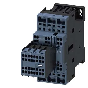
These figures define its capability for motor starting (AC-3 duty) and resistive heating (AC-1) applications. The 480 V 21 A rating means it can interrupt a motor circuit at that voltage and current within its thermal limits — a key parameter for panel builders coordinating with upstream protection. The main contacts also accept 2x (0.5 to 2.5 mm²) fine-stranded wire. This range covers typical control panel wiring from 14 AWG to 8 AWG, so it fits standard motor branch circuits without special lugs.
Dimensions are 102 mm high, 45 mm wide, and 144 mm deep — the S0 frame footprint. These are the minimum air gaps needed around the contactor for heat dissipation and arc flash containment; a panel layout that respects these keeps the contactor within its thermal design. The storage range exceeds the operating range because it covers shipping and warehousing conditions — the contactor is not expected to switch loads at -55 °C. This allows installation in tight enclosures where the DIN rail is not perfectly vertical. Switching frequency limits vary by duty: 1,000 cycles/hour at AC-1 maximum, 750 cycles/hour at AC-2 and AC-3 maximum, 250 cycles/hour at AC-4 maximum, and 750 cycles/hour at AC-3e maximum. For a motor starter application (AC-3), 750 cycles/hour means roughly one start every 4.8 seconds — adequate for most conveyor and pump cycling, but not for high-speed indexing.
Switching capacity across voltages
The contactor's rated switching capacity is specified at multiple voltages for DC and AC applications. At 48 V it handles 2 A, at 60 V also 2 A, at 110 V it handles 1 A, at 125 V it handles 0.9 A, at 220 V it handles 0.3 A, at 230 V it is rated at 3 hp, at 400 V it handles 3 A, and at 440 V it handles 0.6 A. These values are for the main contacts and reflect the contactor's ability to interrupt DC arcs, which are harder to extinguish than AC arcs. The 3 hp rating at 230 V is a motor horsepower rating — a standard way to specify contactor size for North American motor circuits. Arcing time is specified at 10 to 10 ms, and at AC (50 Hz) it is 0.25 ms. The 10 ms figure is the typical arc duration during contact opening; the 0.25 ms at 50 Hz is the time for the arc to extinguish at a current zero crossing. This is within normal range for a contactor of this class — fast enough to limit contact erosion but not so fast that it requires special snubber circuits.
The contactor has no auxiliary switch built in — the auxiliary switch field is marked 'No'. If your application requires auxiliary contacts for status feedback or interlocking, you will need to add a separate auxiliary contact block that mounts on the contactor's side or front. This is typical for the S0 frame; Siemens offers add-on blocks that clip onto the contactor without additional wiring space.