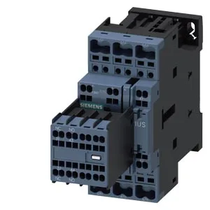
Siemens 3RT2026-2AF08-0KT2 — Contactors

Siemens 3RT2026-2AF08-0KT2 SIRIUS S0 Power Contactor, Spring

MPN3RT2026-2AF08-0KT2
Active

Siemens SIRIUS S0 power contactor, 3RT2026-2AF08-0KT2, 45 mm wide, spring-type terminals for the magnet coil, screw and snap-on mounting onto 35 mm DIN rail.

Source DocumentedChannel stated on listing & quote
Condition PhotosReal unit photos / video on request
WhatsApp AnswersFast human replies for machine-down parts
Worldwide DispatchDHL/FedEx — transit quoted per order
Independent China distributor & sourcing agent· Listing updated Sep 2026

Specifications

3RT2026-2AF08-0KT2 — Identification
ParameterValue
Contactor frame sizeS0
3RT2026-2AF08-0KT2 — Ratings & Performance
ParameterValue
Rated operational current, AC-12, max.10 A
Rated operational current, AC-4 @ 400 V15.5 A
Rated value @ 400 V3 A
Rated value @ 500 V2 A
Rated value @ 690 V1 A
Rated value @ 230 V3 hp
Rated value @ 24 V6 A
Rated value @ 60 V2 A
Rated value @ 110 V1 A
Rated value @ 220 V0.3 A
3RT2026-2AF08-0KT2 — Control & Coil
ParameterValue
Control supply voltage typeAC
Rated value @ 50 Hz0.25
Rated value @ 50 Hz110 V
3RT2026-2AF08-0KT2 — Contacts & Poles
ParameterValue
Main poles3
Main NO contacts3
Auxiliary contact reliability1 faulty switching per 100 million (17 V, 1 mA)
3RT2026-2AF08-0KT2 — Protection & Coordination
ParameterValue
Short-circuit coordination type 1, fusegG: 100 A (690 V, 100 kA), aM: 50 A (690 V, 100 kA), BS88: 100 A (415 V, 80 kA)
Short-circuit coordination type 2, fusegG: 35A (690V, 100kA), aM: 20A (690V, 100kA), BS88: 35A (415V, 80kA)
Aux. switch short-circuit protection, fusegG: 10 A (500 V, 1 kA)
3RT2026-2AF08-0KT2 — Connection & Mounting
ParameterValue
Main circuit connectionspring-loaded terminals
Aux. / control circuit connectionspring-loaded terminals
Conductor cross-section, solid1 ... 10 mm²
Conductor cross-section, solid or stranded2x (0.5 ... 2.5 mm²)
Conductor cross-section, finely stranded w/ ferrule2x (0.5 ... 1.5 mm²)
Mounting methodscrew and snap-on mounting onto 35 mm standard mounting rail according to DIN EN 60715
Side-by-side mountingYes
3RT2026-2AF08-0KT2 — Durability
ParameterValue
Durability (operating cycles, typ.)10 000 000
Durability with aux. switch block (cycles, typ.)10 000 000
3RT2026-2AF08-0KT2 — Environmental
ParameterValue
Operating temperature range-25 ... +60 °C
Storage temperature range-55 ... +80 °C
Installation altitude, max.2 000 m
3RT2026-2AF08-0KT2 — Mechanical
ParameterValue
Width45 mm
Height102 mm
Depth144 mm
3RT2026-2AF08-0KT2 — Specifications
ParameterValue
At AC4 ... 16 ms

Product details

SIRIUS S0 Power Contactor with Spring-Terminal Coil

The contactor occupies a 45 mm wide footprint on the rail, with a depth of 144 mm and height of 102 mm. It mounts via screw fixing or snap-on onto 35 mm standard mounting rail per DIN EN 60715, and the mounting position allows +/-180° rotation on a vertical surface plus +/-22.5° tilt forward or backward — useful when fitting into existing enclosures with non-ideal rail orientation.

Switching Capability and Duty Cycles

This contactor carries different maximum switching rates depending on the duty class. For resistive loads (AC-1) it handles up to 1,000 switching cycles per hour. For motor starting and stopping (AC-3 and AC-3e) the limit is 750 cycles per hour, and for plugging or inching duty (AC-4) it drops to 250 cycles per hour. The auxiliary contact block (if fitted) has rated breaking capacities ranging from 6 A at 24 V up to 0.3 A at 220 V, with intermediate values at 48 V (2 A), 60 V (2 A), 110 V (1 A), 125 V (0.9 A), 400 V (3 A), and 440 V (0.6 A). These are the current values the auxiliary contacts can interrupt at the respective voltages — useful when confirming compatibility with a PLC input or relay coil in the control circuit. The main contactor is rated for a mechanical life of 10 million operating cycles typical. The arcing time is specified at 10 ms, and the closing time at AC is 4 to 16 ms.

Wiring and Clearance

The coil terminals accept 2x (0.5 to 2.5 mm²) solid or stranded. These clearances matter for thermal management and arc flash containment — particularly the side clearance of 6 mm, which is tighter than the vertical gaps.

Frequently asked questions

What are the key dimensions for panel layout?

Width is 45 mm, depth 144 mm, height 102 mm. Minimum clearances to adjacent parts are 10 mm upwards, 10 mm forwards, 10 mm downwards, and 6 mm at the side.

What wire sizes does the contactor accept?

Main circuit terminals accept solid or stranded conductors from 1 to 10 mm². The spring-type coil terminals accept 2x (0.5 to 2.5 mm²) solid or stranded.

What is the maximum switching rate for motor loads?

For AC-3 and AC-3e duty (standard motor starting), the maximum is 750 switching cycles per hour. For AC-4 duty (plugging/reversing), it drops to 250 cycles per hour.

MPN
3RT2026-2AF08-0KT2