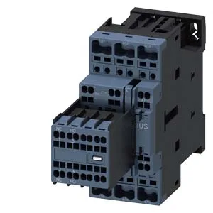
Its 45 mm width and 144 mm depth define the DIN-rail footprint — plan for that depth when sizing the enclosure depth, especially with gland plates or busbar systems behind the rail. These are the minimum air gaps for arc flash and heat dissipation — don't crowd the contactor against cable ducts or adjacent devices.
Coil and switching ratings
The magnet coil uses spring-type terminals (cage clamp) — no screw torque to verify, which speeds panel wiring. Coil ratings at 24 V rated value: 6 A. At 48 V: 2 A. At 60 V: 2 A. At 110 V: 1 A. At 125 V: 0.9 A. At 220 V: 0.3 A. At 400 V: 3 A. At 440 V: 0.6 A. These are the contact ratings at those voltages — match your load voltage to the appropriate row for the actual switching capacity. Motor load rating at 230 V: 3 hp. At 400 V: 3 A. The AC-1 (resistive) maximum operating frequency is 1,000 operations per hour; AC-4 (plugging/reversing/inching) at 250 ops/h. For high-duty-cycle applications like frequent reversing, the AC-4 limit governs — don't exceed 250 cycles per hour.
For fine-stranded or ferrule-terminated wire, the dual-entry specification allows 2x (0.5 to 2.5 mm²). The spring-type terminals on the coil side match the same cage-clamp family — consistent tooling across the contactor.
Environmental limits
Storage temperature: -55 to +80 °C.