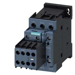
At 230 V it carries a 5 hp motor rating, so it fits smaller single-phase or two-speed motor circuits as well.
The AC-3 rating (27 A at 480 V) is the motor-switching duty that governs real-world selection — it covers starting inrush and breaking the stalled-rotor current. The AC-1 maximum operating rate of 1,000 switching cycles per hour tells you the thermal limit for resistive loads; for motor duty (AC-3) that drops to 750 cycles per hour, which is typical for a general-purpose contactor in a Size S0 frame. Storage range extends to -55 to +80 °C, which is the shipping and warehouse limit, not the running condition. The contactor's mechanical service life is listed at 10,000,000 typical operations — that's the mechanical endurance before the armature or spring wears out. Electrical life depends on the switching current and duty cycle; at rated AC-3 load you'll get fewer cycles, but the mechanical figure tells you the base platform is built for high-throughput applications like conveyor sortation or packaging lines.
Width is 45 mm, height 85 mm, depth 141 mm — that's a compact S0 footprint for a contactor rated this high. Main contact terminals accept solid or stranded wire from 1 to 10 mm², or two conductors of 0.5–1.5 mm² or 0.75–2.5 mm² in parallel. The coil connection uses screw-type terminals.
If you're holding a panel drawing that specifies the 3RT2027-1AK64-3MA0 variant (different coil voltage or auxiliary configuration), the 3RT2027-1AV04 shares the same Size S0 frame and mounting footprint — it will drop into the same DIN-rail position without panel rework. The deciding factor is the coil rating and any integrated aux contacts; verify those against your control voltage before committing the BOM line.