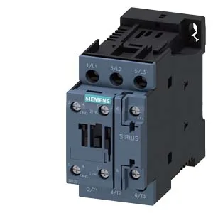
The 3RT2027-1KB40: The contactor carries no built-in auxiliary switch, so any auxiliary contact blocks needed for status feedback or interlocking must be added externally. The coil termination uses screw-type terminals, which is the standard for this frame size.
The 24 VDC coil is the controlling voltage — this contactor pulls in and seals at that nominal level. Switching frequency depends on the duty class: at AC-1 (resistive loads) the maximum is 1,000 operations per hour; at AC-3 (standard motor starting) it is 750 ops/h; at AC-4 (plugging/inching) it drops to 250 ops/h. These limits govern the contactor's thermal endurance — exceeding them shortens life.
Wiring and Integration Notes
For auxiliary circuits, the terminal capacity is 2x (0.5 to 1.5 mm²) or 2x (0.75 to 2.5 mm²). The main contact tightening torque range is 16 to 8 Nm (the evidence lists the range in descending order — verify the exact value on the nameplate). These are the minimum air gaps required around the contactor for heat dissipation and arc containment. The arcing time is specified at 10 to 10 ms — a tight window that suggests consistent arc extinction behavior across the rated current range.
The 3RT2027-1KB40 is a 24 VDC variant. If your panel was specified around a different coil voltage (e.g., 24 VAC or 230 VAC), verify coil compatibility before substituting — the mechanical footprint is shared across the S0 frame, but the coil voltage must match the control circuit.