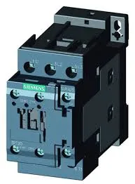
Part Identity and Fit
It mounts via screw or snap-on onto 35 mm DIN rail per DIN EN 60715, and the mounting position allows +/-180° rotation on a vertical surface plus +/-22.5° tilt forward/backward, giving flexibility in tight enclosures. The coil is rated 21–28 V DC, with a peak inrush of 3 A. At the 24 V rated value, the contactor switches 10 A; at 48 V and 60 V, it handles 2 A. This makes it suitable for 24 V DC control circuits common in automotive and machine tool lines. Main contact wiring accepts solid or stranded conductors from 1 to 10 mm², and auxiliary contacts accept 2x (0.5 to 1.5 mm²) or 2x (0.75 to 2.5 mm²). The coil uses screw-type terminals, consistent with panel-builder practices for secure terminations.
Rated for up to 1,000 operations per hour in AC-1 resistive load duty, 750 ops/h in AC-2 and AC-3 motor switching, and 250 ops/h in AC-4 (plugging/inching). The AC-3e rating also allows 750 ops/h. These limits define the thermal cycling capability — exceeding them risks contact welding or premature wear, especially in high-inertia or reversing applications. Arcing time is specified at 10 ms, with operate and release times of 30–50 ms for both AC and DC coils. This is typical for a contactor of this class and ensures predictable switching behavior in sequenced control schemes.
Clearance distances required: 10 mm upwards, downwards, and forwards; 6 mm at the side. These are minimums for arc flash containment and must be respected in panel layout to avoid phase-to-phase or phase-to-ground faults. Dimensions are 85 mm height, 45 mm width, and 107 mm depth — the S0 footprint fits standard 45 mm-wide DIN-rail slots, common in modular panel designs.