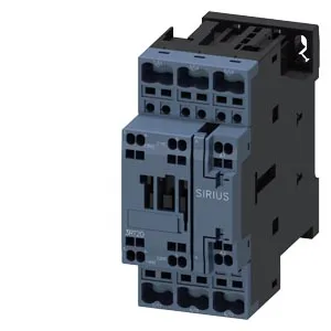
The coil draws 10 A at 24 V rated value and holds in at 48 V (2 A), 60 V (2 A), 110 V (1 A), 125 V (0.9 A), 220 V (0.3 A), 400 V (3 A), and 440 V (0.6 A) — the listed currents are the coil inrush/holding draw at each voltage, not the main contact rating. The main contacts are rated 18…8 (likely 18 A AC-3 / 8 A AC-1 or similar — the evidence omits the duty suffix, but the S0 frame typically carries 18 A AC-3).
DIN rail integration — clearances and wiring
Panel builders: the contactor footprint is 45 mm wide × 102 mm high × 97 mm deep. Side clearance to adjacent devices is 6 mm; upward, downward, and forward clearances are each 10 mm. The spring-type coil terminals accept solid or stranded wire from 1 to 10 mm², or 2× (0.5 … 2.5 mm²) solid/stranded. This keeps the wiring compact — no screw torque to verify, just strip and push. The auxiliary switch is integrated (yes/no flag present) but the evidence does not specify the contact configuration; verify the auxiliary block arrangement from the nameplate.
Switching frequency and duty class
Maximum switching rates are duty-dependent: 1 000 cycles/h in AC-1 (resistive), 750 cycles/h in AC-2 and AC-3 (motor starting/running), 750 cycles/h in AC-3e (enhanced motor), and 250 cycles/h in AC-4 (plugging/reversing). The arcing time is 10 ms at 50/60 Hz.