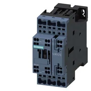
It mounts via screw and snap-on onto a 35 mm DIN rail per DIN EN 60715, and its mounting position allows ±180° rotation on a vertical surface plus ±22.5° tilt forward and backward — useful when routing cables in a tight enclosure. An auxiliary switch is built in, saving a separate add-on block for basic feedback.
Switching frequency is rated per duty cycle: 1 000 cycles/hour at AC-1 (resistive loads), 750 cycles/hour at AC-2 and AC-3 (motor starting/running), and 250 cycles/hour at AC-4 (plugging/inching). For AC-3e (enhanced motor starting) it also carries 750 cycles/hour. These numbers define the thermal limit of the contactor under repeated operation — exceeding them accelerates contact wear, especially under AC-4 duty where inrush current is highest. The auxiliary contact ratings span from 10 A at 24 V DC down to 0.3 A at 220 V DC, with intermediate values at 48 V (2 A), 60 V (2 A), 110 V (1 A), 125 V (0.9 A), and 400 V (0.3 A). This is a standard resistive DC load curve — inductive loads (e.g., relay coils) will require derating or a suppression diode across the load. The 60 °C ceiling is typical for a panel-mounted contactor without forced cooling; if your enclosure ambient exceeds that, you'll need to derate or add ventilation. Mechanical life is listed at 10 million operations typical — a solid figure for a Size S0 contactor, meaning it will outlast most electro-mechanical cycles in a standard machine before the contacts need inspection.
Physical Fit and Clearance
Dimensions: 102 mm high, 45 mm wide, 107 mm deep. Arcing time is 10 to 10 ms, and DC dropout time is 15 to 18 ms — consistent with a standard AC coil. The tight arcing window means contact erosion is predictable under rated loads.
If you're holding a legacy panel built around the 3RT2027-2AP00-ZX95 variant, the 2BM40 drops into the same Size S0 footprint and DIN rail mount — no rewiring needed for the main power path. The difference is in the coil and auxiliary contact configuration, so verify your control voltage and aux contact count against the existing schematic before committing the BOM line.