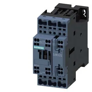
The Siemens 3RT2027-2KA40 is a SIRIUS coupling contactor in size S0 — a compact, DIN-rail-mountable switching device designed for isolating and switching DC control circuits, typically between a PLC output module and a downstream load or as an interface between different voltage domains in a panel. It is rated for 10 A at 24 V DC and 2 A at 48 V DC, with a DC switching capacity that drops to 0.3 A at 220 V DC — so the buyer needs to match the contactor's DC-13 or resistive rating to the actual load voltage and current, not just the coil voltage. The coil is 24 V DC, and the contactor is fitted with spring-type terminals — cage-clamp style — which speeds wiring and eliminates screw-torque checks on the line.
At 45 mm wide, 102 mm high, and 107 mm deep, it fits a standard S0 footprint and leaves room for adjacent devices on the same DIN rail. Wire range: solid or stranded 1 … 10 mm², with dual-wire capability 2x (0.5 … 2.5 mm²). Spring terminals accept ferruled or solid conductors — strip length follows the manufacturer's recommendation for the terminal type.
Switching performance and lifecycle
Electrical switching frequency depends on the duty category: up to 1,000 operations per hour at AC-1 (resistive), 750/h at AC-2 and AC-3 (motor starting/running), and 250/h at AC-4 (plugging/inching). Arcing time is 10 … 10 ms, and the DC make/break time is 19 … 21 ms — consistent with a standard DC contactor response.
The contactor has no built-in auxiliary switch — if feedback or status signaling is needed, a separate auxiliary contact block must be added.