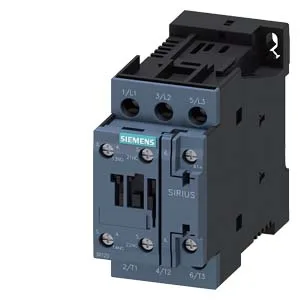
It mounts on a 35 mm DIN rail per DIN EN 60715 via screw and snap-on fastening, fitting into a 45 mm wide slot with a 107 mm depth and 85 mm height.
The DC switching ratings tell you exactly what this contactor can handle across common control voltages: 10 A at 24 V, 2 A at 48 V and 60 V, 1 A at 110 V, 0.9 A at 125 V, 0.3 A at 220 V, and 3 A at 400 V. These are the maximum currents the main contacts can interrupt at those DC voltage levels — critical for sizing the contactor to your load, especially in battery or rectified-supply circuits where DC arc extinction is harder than AC. For AC motor duty, the contactor is rated 5 hp at 230 V, which covers typical small pump, fan, or conveyor motors in that power class. The operating frequency limits per duty cycle are: 1,000 operations per hour at AC-1 (resistive), 750/h at AC-2 and AC-3 (motor starting/running), and 250/h at AC-4 (plugging/reversing). The AC-3e rating also sits at 750/h. These numbers govern how often the contactor can cycle without overheating — a panel-builder consideration for high-speed production lines.
The contactor accepts solid or stranded conductors from 1 to 10 mm² on the main circuit, and fine-stranded wiring from 2x (0.5 to 1.5 mm²) or 2x (0.75 to 2.5 mm²) for auxiliary circuits. The coil dropout time on DC supply is 15 to 18 ms, and the arcing time is 10 ms. These timing specs matter for coordination with upstream protective devices and for sequencing in safety circuits where contactor dropout delay affects stop times.