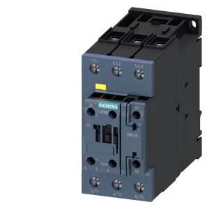
It mounts on 35 mm DIN rail per DIN EN 60715 via screw or snap-on fastening, and the mounting position allows +/-180° rotation on a vertical surface plus +/-22.5° tilt forward and backward — handy when you're squeezing it into a tight enclosure. Rated coil voltage is 21-33 V DC, with a pickup threshold of 0.8 x rated value (about 16.8 V) and a dropout around 0.1 x rated value (roughly 2.1 V). Inrush current peaks at 2.2 A, holding power at 2 VA on 50/60 Hz. That's a standard DC coil draw — plan your 24 VDC supply to handle the inrush if you're ganging several contactors.
The 55 mm width and 130 mm depth are standard for the S2 frame — check your DIN-rail clearance and door swing before committing. Mechanical life is typical at 5 million operations, and the listed MTBF is 52 years — a reliability figure that assumes proper derating and clean power. For a contactor in a pump panel cycling a few times an hour, that's a solid baseline. The main contacts are rated for switching frequencies up to 1000 cycles/hour under AC-1, AC-3, and AC-3e duty, 750 cycles/hour under AC-2, and 300 cycles/hour under AC-4. That means it's comfortable in conveyor and fan duty (AC-3) but you'll want to derate for heavy jogging or inching (AC-4). Auxiliary contacts are built in — the main contact block carries 1 NO + 1 NC configuration (18 to 1). That's enough for a feedback signal or a holding circuit without an add-on block.
Screw-type terminals on the magnet coil accept 2 x (0.5 to 1.5 mm²) or 2 x (0.75 to 2.5 mm²) solid or stranded wire. That's typical for control wiring — no special crimp tool needed, but use ferrules on stranded for a reliable connection. Those are the minimum air gaps for arc flash and heat dissipation.